Master controls 15
—Owner’s Manual
3 TAPE IN switch
This selects the signal that will be monitored by
the C-R OUT jacks and PHONES jack: either the
PFL/AFL bus, or the TAPE IN jacks.
4 C-R MONITOR LEVEL (control room moni-
tor level) control
This adjusts the level of the signal that is sent to
the C-R OUT jacks. It does not affect the output
signal of the PHONES jack.
5 PHONES LEVEL (headphone) jack
This adjusts the level of the signal that is sent to
the PHONES jack. It does not affect the output
signal of the C-R OUT jacks.
6 PHONES (headphone) jack
A set of stereo headphones can be connected to
this jack for monitoring. This jack will output the
same signal as the C-R OUT jacks. The wiring of
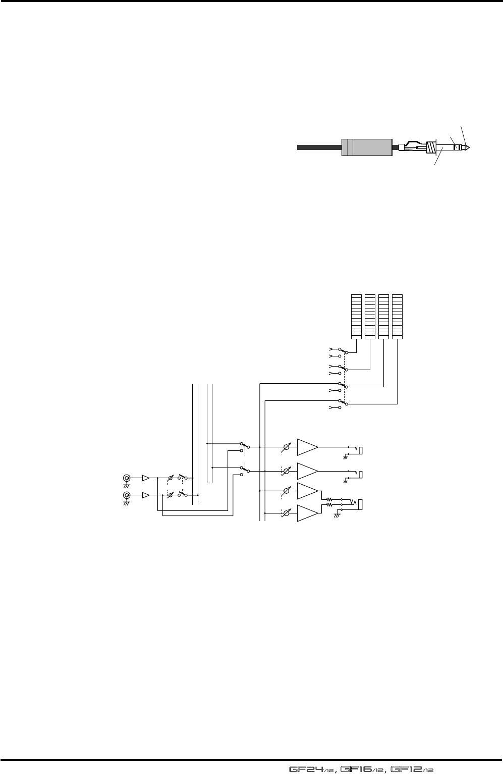
this jack is as shown in the following diagram.
Tape input and monitor output signal flow
1/4" TRS phone plug
Tip (hot)
Ring (cold)
Sleeve (ground)
ON
METER SELECT
from GROUP OUT 1
from GROUP OUT 4
from GROUP OUT 3
from GROUP OUT 2
from STEREO OUT L
from STEREO OUT R
C-R OUT
PHONES
ST
TAPE IN
R
L
TAPE IN
C-R MONITOR
LEVEL
LEVEL
PFL/AFL
LR
BA
BA
BA
BA
PHONES
L
R
ST
RL


