


Connections
14 IMX644 Owner’s Manual
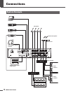
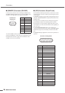
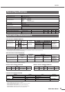
■ [REMOTE] Connector (RS-232C)
Connect to this connector when controlling the IMX644 from
the IMX644 Manager application or an external AMX/Crestron
controller. Use an RS-232C cross cable for connection.
An external AMX or similar controller can be used to send com-
mands to the IMX644 to recall memories and adjust the level of
individual channels. Refer to page 20 for information on the
available remote control commands.
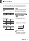
■ [GPI] Connector (25-pin D-sub)
External GPI (General Purpose Interface) control devices can be
connected to this connector to allow input and output of remote
control signals.
The IMX644 GPI port has eight inputs and eight outputs, plus a
dedicated “POWER MONITOR” output that indicates the unit’s
ON/OFF status.
The input pins are normally left open. Shorting an input pin to
ground (GND) recalls the corresponding memory number.
The output pins are open-collector outputs that deliver a maxi-
mum output of +35 volts, with a maximum current capability of
30 mA per port.
For the POWER MONITOR outputs, pins 24 and 25 are
“closed” (shorted) when the power is ON. The POWER MONI-
TOR COLD pin (pin 25) is internally connected to the GND
pins.
The IMX644 Manager application can be used for parameter as-
signment.
1234
6789
5
Connector Pin
Assignments
Pin No. Signal name
1Unused
2 RxD
3 TxD
4 DTR
5 GND
6 DSR
7RTS
8 CTS
9Unused
Pin No. Signal name
1 GND
2 GND
3 INPUT 1
4 INPUT 2
5 INPUT 3
6 INPUT 4
7 INPUT 5
8 INPUT 6
9 INPUT 7
10 INPUT 8
11 GND
12 GND
13 GND
14 OUTPUT 1
15 OUTPUT 2
16 OUTPUT 3
17 OUTPUT 4
18 OUTPUT 5
19 OUTPUT 6
20 OUTPUT 7
21 OUTPUT 8
22 GND
23 GND
24 POWER MONITOR HOT
25 POWER MONITOR COLD
12345678910111213
252423222120191817161514
Connector Pin Assignments