


3
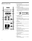
■ (Stereo input section)
–10dB
+4dB –20dB
HIGH
–15 +15
LOW
+15
AUX 1
010
BALANCE
LR
–15
PEAK
PFL
10
5
0
5
10
15
20
30
00
7
8
8
9
0
A
C
B
D
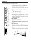
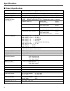
8 GAIN select switch
Use this switch to adjust the sensitivity of the input as appropriate for the level
of the input signal.
For the best balance of S/N ratio and dynamic range, adjust this switch so that
the peak indicator B lights occasionally.
9 HIGH, LOW equalizer (2 band)
These knobs control high mid and low equalization at the following frequen-
cies.
HIGH: 12kHz, maximum effect ±15dB
LOW: 80Hz, maximum effect ±15dB
When the knob is in the center position, the response will be flat.
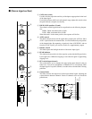
0 AUX1 control
This knob controls the level of the signal that is output to the AUX bus. Since
AUX1 is placed before the channel fader, it will be unaffected by the position
of the channel fader. By outputting a signal only from AUX SEND 1 and not
from the ST OUT jacks, you can also use this as a supplementary output.
A Balance control
This knob adjusts the left/right location of the stereo input signal.
B PEAK indicator
This indicator detects the level of the signal at a point after the EQ (pre fader).
It will light red at 3dB before clipping to warn that the signal is approaching
clipping level.
C PFL switch (input channel)
This switch allows you to monitor the signal of the input channel at the pre
fader level. You can use headphones or MONI OUT to conveniently check
the input signal of a specific channel, or trouble-shoot a channel that is having
problems.
D Channel fader
This fader controls the output level of the input channel signal, adjusting the
volume balance between channels. Faders of channels not in use should be
pulled down.
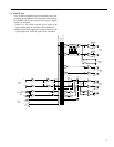
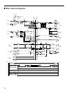
BALANCE
PEAK
LOW
HIGH
AUX 1
L/MONO
PFL
(+V)
BA
BA
–20dB
–10dB
+4dB
EQHA
HA EQ
R
7–14
LINE IN
PFL CTRL
R
L
PFL
2
1
AUX
R
L
STEREO