


MX12/6, 20/6 — Owner’s Manual
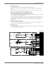
Front & Rear Panels 5
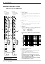
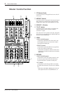
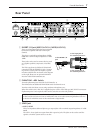
u DIGITAL EFFECT
• PROGRAM Select Switch
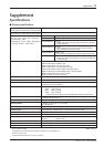
Selects a program from the built-in digital effects.
VOCAL ECHO 1
VOCAL ECHO 2
VOCAL ECHO 3
VOCAL ECHO 4
VOCAL REVERB 1
VOCAL REVERB 2
VOCAL REVERB 3
VOCAL REVERB 4
• PARAMETER Control
Controls parameters (effect level, speed, etc.) of the selected effect program.
• ON Switch
Switches the built-in digital effect ON (>) or OFF (?). When set to OFF, the signal from the built-
in effect is not sent.
• AUX1, AUX2 Control
Controls the level of the signal that is sent from the built-in digital effects to the AUX1 and AUX2
buses.
• ST Control
Controls the level of the signal that is sent from the built-in digital effects to the STEREO bus.
i TAPE IN Control
Controls the level of the signal that is sent from the TAPE IN jack to the STEREO bus.
o ST GRAPHIC EQUALIZER
A stereo 7-band graphic equalizer that offers tone adjustment to the signal that is output to the ST OUT
jacks.
A +/-12dB boost or cut is provided at each of the frequency bands 125, 250, 500, 1k, 2k, 4k and 8kHz.
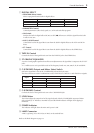
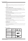
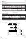
!0 C-R/PHONES Output and Meter Select Switch
Selects the signal that is sent to the C-R/PHONES jack and the level meter.
The three switches are used in combination to select TAPE IN, ST, GROUP 1-2 and GROUP 3-4 signals.
HALL 1
HALL 2
HALL 3
ROOM
PLATE 1
PLATE 2
PLATE 3
GATE REVERB
Signal
Switch
? 1-2 > 3-4 ? ST > GROUP ? > TAPE IN
TAPE IN N/A N/A > TAPE IN
ST N/A ? ST ?
GROUP 1-2 ? 1-2 > GROUP ?
GROUP 3-4 > 3-4 > GROUP ?
!1 C-R/PHONES Control
Controls the level of the signal that is sent to the C-R/PHONES jack.
!2 LEVEL Meter
The LEDs indicate the output level of the signal selected with the C-R/PHONES output and Meter
Select Switch !0. “0” indicates a nominal level, and the PEAK indicator will light when clipping is
imminent.
!3 POWER Indicator
The indicator will light when the main unit’s power is ON.
!4 LAMP Connector
A BNC type lamp (AC or DC12V, 0.5A Max) can be attached here.
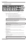
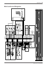
Refer to the Block Diagram on page 13.