


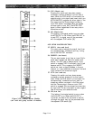
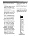
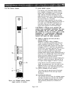

52. ON (Aux 1Master On)
Engaging this locking, illuminated switch turns
on the Aux 1 master output. When the output is
turned off, the feed to the VU meter is also off,
although the signal may still be previewed with
the adjacent CUE switch [51].
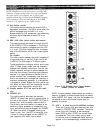
53. AUX 2 STEREO SEND MASTER SECTION
This cluster of controls and switches functions
identically to the Aux 1 Stereo Send Master
Section [48-52], except they affect the Aux 2
Stereo Output.
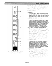
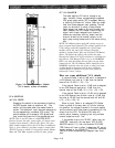
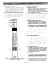
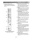
Figure 2-4b. PM4000 Stereo Master Module
(lower portion of module)
Page 2-18
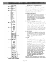
STEREO MASTER SECTION
54. STEREO-TO-MTRX
Engaging this locking switch assigns signal from
the Stereo Output (ahead of the Stereo ON
switch) to all L and R rotary mix controls in the
matrix. The switch is illuminated when the stereo
signal is assigned to the matrix.
NOTE: The signal is routed to the matrix via an internal
switch in the module. The switch is preset so the feed to
the matrix comes after the Stereo Master Fader; the
switch may be moved to obtain a pre-Stereo Master
Fader feed. Refer to Section 6 for more information on
this optional function.
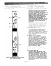
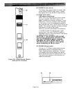
55. INSERT (Stereo master insert)
The Stereo master output circuit has a pair of
insert Out/In patch points (L & R) located just
before the master faders. The OUT jacks are
always active. If this switch is engaged (LED
illuminated), the L & R IN jacks become active.
Thus, engaging the INSERT switch can insert a
stereo signal processor (or a pair of mono proces-
sors) in the stereo master output, or it can substi-
tute an external line-level input instead of the
mixed stereo signals.
NOTE: The Stereo Sub In jacks apply signal to the aux
mix ahead of the insert point, so sub-in program will be
fed to the stereo
insert out jacks.
56. CUE (Stereo master cue)
Pressing this switch part-way down causes
momentary contact; pressing it further locks it
down. When the CUE switch is illuminated, the
aux 2 master cue mix signal (post insert point,
pre master control) replaces any other signal in
the Cue output and the Phones output unless an
input CUE switch is engaged. (Bus cue signals
are overriden by input cue.) The stereo master
cue signal is stereo.
57. ON (Stereo master On)
Engaging this locking, illuminated switch turns
on the stereo master output. When the output is
turned off, the feed to the VU meter is also off,
although the signal may still be previewed with
the adjacent CUE switch [56].
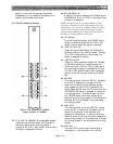
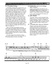
58. (Dual Fader)
This pair of closely-spaced faders adjusts the
level applied from the stereo mixing bus to the
stereo output connectors. The Fader knobs are
located immediately next to each other so both
can be operated in unison with a single finger. At
the same time, the two (Left and Right) knobs
may be offset somewhat and still operated to-