


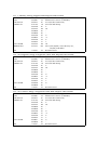


*3 The data between D0 and D407 (See the Scene Memory Map)
*4 The data between D0 and D127 (See the Program Change Assign Map)
*5 The data between D0 and D1151 (See the Control Change Assign Map)
*6 The data between D0 and D25 (See the Setup Memory Map)
*7 The data between D0 and D71 (See the Backup Memory Map)
*8 The data between D0 and D35 (See the Effect User Memory Map)
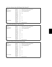
*9 The data between D0 and D21 (See the Compressor User Memory Map)
*10 The data between D0 and D23 (See the EQ User Library Map)
*11 The data between 0 and 64 (See the Key Number List)
*12 SWITCH: ON=00h, OFF=7Fh
DATA ENTRY: 01-7Fh
*13 See the Error Message List
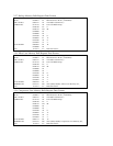
*14 The following is how to calculate data format.
For example, Strings character: Ms,M1,M2,M3,...,Mx,...,Me
(Mx is ASCII code 1 byte data. The data ranges between 00h and FFh.)
Mx = Mx (Character code)
LF(Return) = 0Ah
*15 The following is how to calculate data format. For example, Internal
Data : Ds, D1, D2, D3, ..., Dx, ..., De (Dx is 1byte data. The data ranges
between 00h and 3Fh.)
Dx = Dx
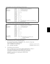
*16 The data between D0 and D2559
*17 This request signal is output when storing a scene memory on the
STORE key, thus enabling the current setup within the EDIT BUFFER to
be stored into a specified memory.
*18 All Data= [1 Memory Mixing Program No.1-50,Edit Buffer] + [All
Program Change Assignment Table] + [All Control Change Assignment
Table] + [Setup Memory] + [Backup Memory] + [1 Effect User Memory
No.0-9] + [1 Compressor User Memory No.0-12] + [1 EQ User Library
No.0-19]