3
CONNECTING THE USB PORTS
You will find a single 10-pin connector on a cable attached to the front USB ports.
This Intel standard connector is keyed so that it can’t be accidentally reversed as
long as it is connected to a proper Intel standard motherboard header. Connect the
10-pin connector to your motherboard headers so that the blocked pin fits over the
missing header pin.
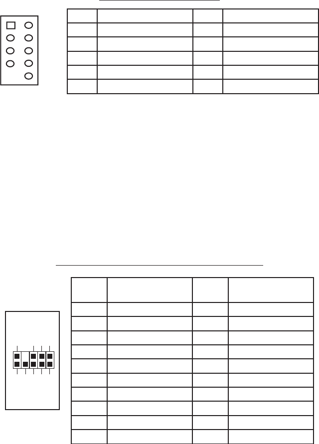
Motherboard USB Pin Layout
Note: Please check your motherboard manual for your USB header pin layout and
make sure it matches the table.
CONNECTING THE eSATA PORT
This case comes with an eSATA port in the front of the case to connect to your
external SATA devices. You will find a SATA connector on a cable attached to the
front eSATA ports. Connect it to a SATA connector on your motherboard.
CONNECTING THE AUDIO PORTS (AC’97 and HDA)
There is an Intel standard 10-pin AC’97 connector and an Intel 10-pin HDA (High
Definition Audio) connector. You can connect either of them to your motherboard
depending on the specification of the motherboard. See instruction below:
Note: Please check your motherboard manual for your audio header pin layout and
make sure it matches the table below. Even if your system supports both audio
standards, you may only connect one connector not both.
Pin Assignment for Audio Ports (HDA and AC’97)
Pin Signal Names Pin Signal Names
1 USB Power 1 2 USB Power 2
3 Negative Signal 1 4 Negative Signal 2
5 Positive Signal 1 6 Positive Signal 2
7 Ground 1 8 Ground 2
9 Key (No Connection) 10 Empty Pin
12
10
9
Pin
Signal Names
(HDA)
Pin
Signal Names
(AC’97)
1 MIC2 L 1 MIC In
2 AGND 2 GND
3 MIC2 R 3 MIC Power
4 AVCC 4 NC
5 FRO-R 5 Line Out (R)
6 MIC2_JD 6 Line Out (R)
7 F_IO_SEN 7 NC
8 Key (no pin) 8 Key (no pin)
9 FRO-L 9 Line Out (L)
10 LINE2_JD 10 Line Out (L)
1
2
3579
46
10


