4
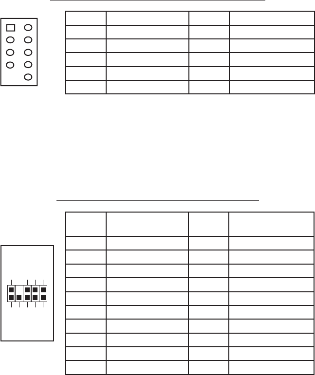
Pin Assignment for Front Panel IEEE 1394 Connector
Connecting the Audio Ports (AC’97 and HDA)
There is an Intel standard 10-pin AC’97 connector and an Intel 10-pin HDA (High
Definition Audio) connector; you can connect either the AC’97 or the HDA
connector to your motherboard depending on the spec of the motherboard. If your
motherboard supports Intel’s standard onboard AC’97 audio connector, plug in the
AC’97 connector directly onto the board. If your motherboard supports Intel’s High
Definition Audio, you can plug HDA onto the board. See instruction below:
Pin Assignment for Audio Ports (HDA and AC’97)
Locate the internal audio connectors from your motherboard or sound card.
Consult your motherboard or sound card manual for the pin-out positions.
3.5” External Device Installation
There is one external 3.5” drive bay under the 5.25” drive bays.
1. Carefully remove the 3.5” drive bay cover from the bezel. Load the drives
from the front, lining them up to the front of the drive cage.
2. With one hand supporting the drive, fasten the drive with the screws provided.
3. Find a small 4-pin white connector on the power supply and connect it to the
male 4-pin connector on the floppy drive.
3.5” HDD Installation
There is one 3.5” HDD mounting point in the bottom 5.25” drive bay, and another
at the bottom of the case. Using the HDD bay at the bottom of the case may
Pin Signal Names Pin Signal Names
1 TPA+ 2 TPA–
3 Ground 4 Ground
5 TPB+ 6 TPB–
7 +12V (Fused) 8 +12V (Fused)
9 Key (No Pin) 10 Ground
12
10
9
Pin Pin Assignment
(HD AUDIO)
Pin Pin Assignment
(AC’97 AUDIO)
1 MIC2 L 1 MIC In
2 AGND 2 GND
3 MIC2 R 3 MIC Power
4 AVCC 4 NC
5 FRO-R 5 Line Out (R)
6 MIC2_JD 6 Line Out (R)
7 F_IO_SEN 7 NC
8 Key (no pin) 8 Key (no pin)
9 FRO-L 9 Line Out (L)
10 LINE2_JD 10 Line Out (L)
1
2
3579
46
10


