6
7) Proceed to the lower chalk line previously snapped on
the roof for the hold-down strap brackets. Mark a hole 2”
(5cm) to the side of the first collector and continue mark-
ing holes on the chalkline centered exactly between the
absorber surfaces until you reach the last collector. Mark
the last hole the same 2” (5cm) to the side of the last col-
lector. Drill a pilot hole and apply sealant at each of
these locations. Bolt the hold-down strap brackets on
the roof. Refer to Figure 6. It is OK to step on the col-
lectors as long as you stay one foot away from the top
and bottom headers. Mark the holes for the bottom hold-
down strap by measuring up 16” (40cm)from the outside
of the bottom header and again centering them between
the absorbers and 2” (5cm) away from the first and last
collector.
Slip one end of a hold-down strap through the slot in the
hold-down strap bracket at the end of the row, then through
the strap clamp and out through the other slot in the hold-
down bracket. Pull about 3” (7-8cm) of the strap through
and bend it back toward the clamp. Refer to Figure 7.
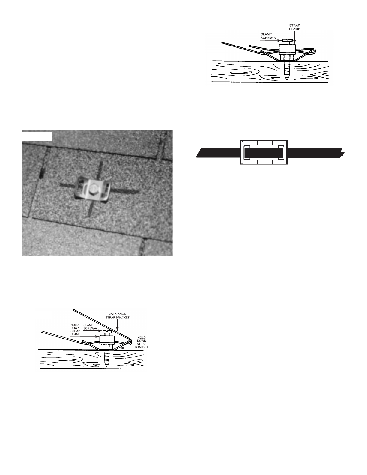
Slip the loose end of the strap through the strap clamp
and pull it tight. Clamp screw (A) should be tightened
securely, but not over-tightened to the point where the
clamp is distorted. Refer to Figure 8. Bring the remain-
ing strap end across the collector face, passing through
both slots in the bracket located on the other side of the
collectors. Pull the straps taut against the face of the col-
lector. Repeat this procedure for the remaining hold-
down strap. Refer to Figure 9.
8) Install the vacuum relief valve in the outlet header of
each row. This will be located at the opposite end of the
row that is connected to the collector outlet pipe. Refer
to figure 2, 11, and 12.
9) Install an end cap in the inlet header of each row,
opposite the end that is connected to the collector inlet
pipe. Refer to Figures 2, 11, and 12.
10) INSPECT THE INSTALLATION AND CHECK ALL
CLAMPS FOR PROPER POSITION AND TIGHTNESS.
11) FOR HURRICANE AREAS, REFER TO ENGINEER-
ING BULLETIN 8101 FOR APPLICATION OF HURRI-
CANE COLLECTOR HOLD-DOWN KIT (Part #12035-1
for 1 1/2”, #12035-2 for 2”)
Installation Over Roof Vent Pipes
Collectors can be installed over or around different diameter
roof vent pipes or other obstructions up to 2” (63mm) in
diameter. After snapping the top chalk lines but before mark-
ing and pre-drilling for your outlet header brackets, locate the
seam in the collector nearest to where the vent pipe is to
come through. Separate by pulling up on top plate, and
pushing down on the lower plate. Should the vent pipe pro-
trude near a sonic tack weld, it will have to be cut apart.
Using a sharp utility knife, cut through the weld while pulling
the two plates apart. Lay the collector over the vent pipe,
keeping the vent pipe at least 12” (30.5cm) away from a
header. It will be easier to complete an installation by
mounting this collector first and then working away from it.
Figure 6
Figure 7
Figure 8
Figure 9


