3
PREPARATION
Keep hands away from pinch and crush points
that are created while folding and unfolding!
!
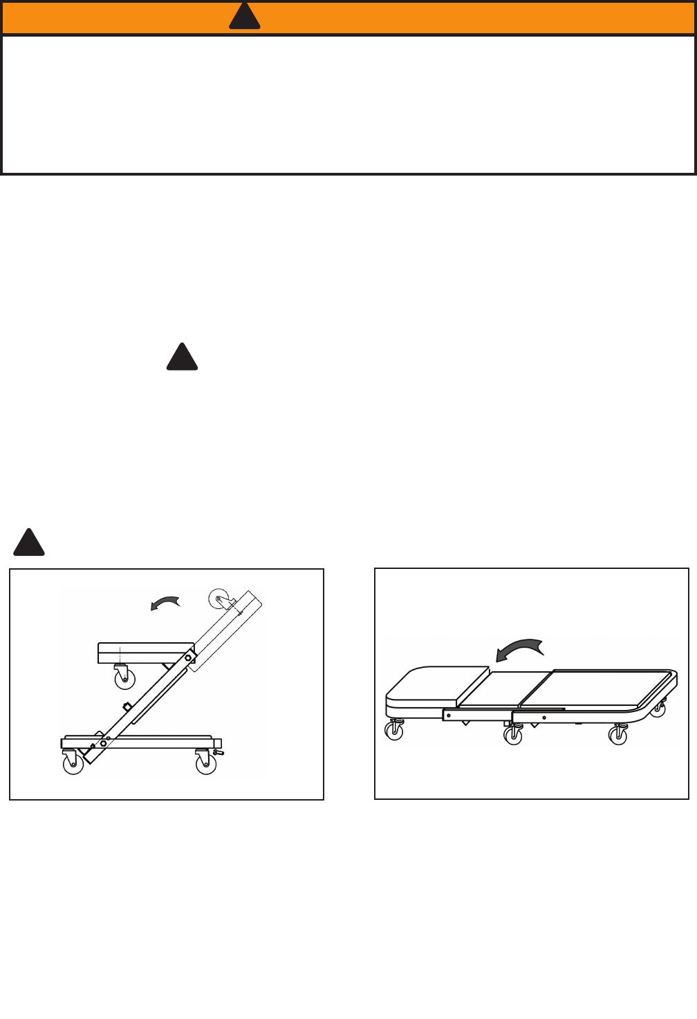
Figure 2
To avoid personal injury and property damage:
WARNING
!
• Read, understand, and follow all printed materials provided with and on this product before use.
• Do not exceed rated capacity! Rated capacity is: 450 lbs. (includes person, tools, equipment, personal items).
• Sit down gently! Avoid shock loads caused by jumping or falling onto seat.
• Do not stand on seat.
• Beware of pinch and crush hazards when folding and unfolding.
• Keep out of the reach of children! This device is not appropriate for children’s use.
• Use on smooth, level surfaces only.
Keep hands away from pinch and crush points that are created during use! Be alert and sober when
using this product! Never operate this equipment when under the inuence of drugs or alcohol.
!
To transform creeper into seat position
Figure 3
To transform seat into creeper position
Step 1. Locate, then unlock the spring loaded Lock
Pin by pulling out until disengaged, at the same time
ip the Head Frame and Middle Frame upward and
back towards the Rear Frame section until the Lock
Pin can engage the Creeper Seat Locking Sleeve
(Fig. 3). Ensure Lock Pin is fully engaged.
Step 2. Flip the Head Frame forward until horizontal.
Step 3. Unlock the spring loaded Lock Pin by pull-
ing out until disengaged, then reverse steps 1, 2 to
convert Creeper Seat into Creeper.
2. Use a suitable open-end wrench to attach the head frame casters to Head Frame. Hand tighten with open end
wrench.
3. Use a 5 mm hex-key to attach the remaining casters to the Rear Frame. Insert the threaded fasteners from
above, the casters from below (as seen in Fig. 1), then hand tighten with hex key.
4. Attach Parts Tray to Rear Frame channel as seen below.
Before beginning assembly of product, make sure all parts are present. Compare parts with package contents
list and Figure 1 illustration. If any part is missing or damaged, do not attempt to assemble, install or operate the
product. Contact customer service for replacement parts.
Contents: 1 creeper body, 6 casters, 4 fasteners
Dimensions: 40” X 18” X 7-1/2”
ASSEMBLY INSTRUCTIONS (see Figure 1)
1. Carefully unfold the creeper as seen in Fig. 1.
OPERATING INSTRUCTIONS (Refer to Fig. 2, 3)
Little instruction is necessary for the safe and proper use if all warning information is understood and followed.


