724-746-5500 | blackbox.com
Page 14
724-746-5500 | blackbox.com
Chapter 2: Overview
NOTE: When the VideoPlex4 is connected to a PC by a USB cable and the VideoPlex4 control application is active, all three lights
flash to identify which unit is being controlled.
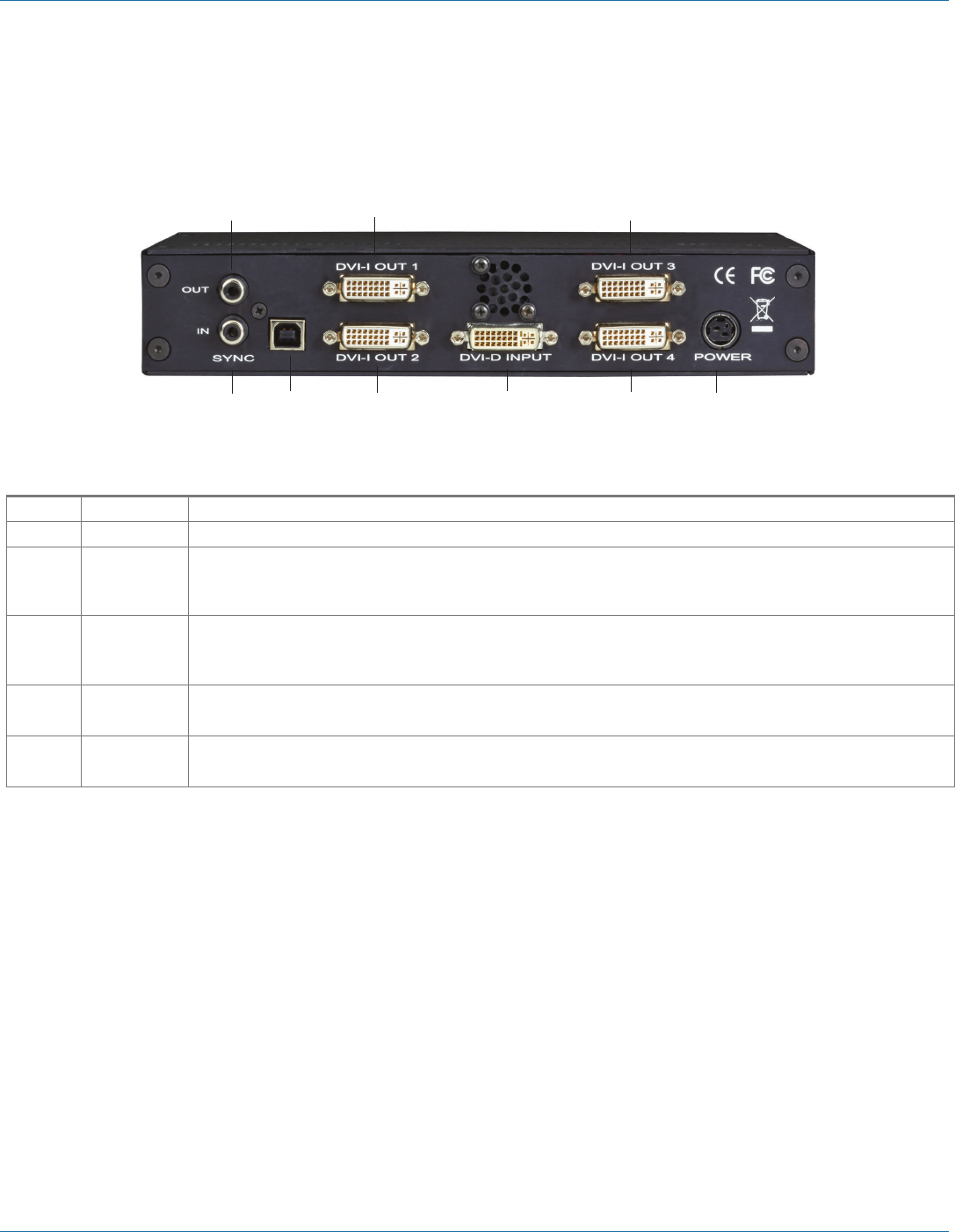
2.4.2 Back Panel
1 2 4 3 4 5
1 4 4
Figure 2-9. Rear panel.
Table 2-2. Back-panel components.
Number Indicator Description
1 Sync Sockets The Sync sockets are provided for future genlock enhancements. Leave them unconnected.
2 USB Socket The USB socket is used to connect the VideoPlex4 to a PC via a USB connection using the supplied USB Type A to
Type B cable. Configuration of the VideoPlex4 is programmable via an application utility, allowing easy control of
cropping, scaling, rotation, and gaps.
3 DVI-D Input
Socket
The DVI-D Input socket is used to connect the DVI input source to the VideoPlex4. The VideoPlex4 supports
dual-link DVI, single-link DVI, and also HDMI (not HDCP compliant) via the optional DVI/HDMI adapter (part
number FA790).
4 DVI-I Output
Socket
The four DVI-I Out sockets are used to connect the VideoPlex4 to the output monitors. The VideoPlex4 supports
both DVI and analog RGB monitors.
5 Power The Power socket is where the supplied power source connects to the VideoPlex4. The power LED on the front of
the VideoPlex4 illuminates when a power supply is connected.
