6-5
Cisco uBR-3x10 RF Switch Hardware Installation and Cabling Guide
OL-1984-06
Chapter 6 Troubleshooting
Troubleshooting the Installation and Setup
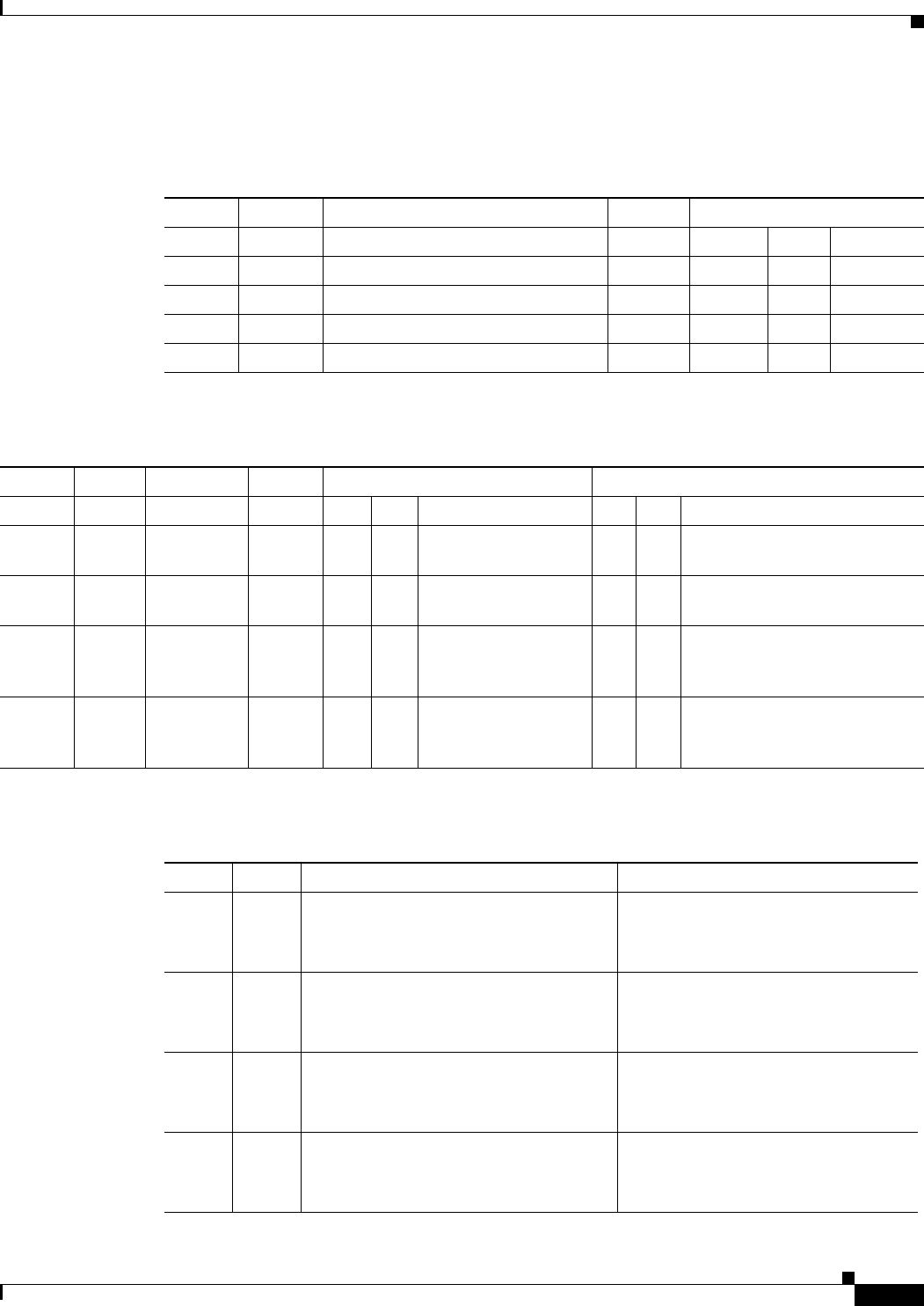
Table 6-2, Table 6-3, and Table 6-4 show hardware configuration switch settings for the Ethernet
controller. These are set at the factory and should not be changed.
Table 6-2 SW4—Option Select
Switch Name Description Default Baud Rate Select
BR1 BR0 Rate
1 -- Not used OFF 0 0 9600
2 -- Not used OFF 1 0 19200
3 BR1 Baud rate select OFF 0 1 38400
4 BR0 Baud rate select OFF 1 1 57600
Table 6-3 SW3— System Configuration
Switch Name Description Default Memory Select Load Sequence Override
MR1 MR2 Description LS1 LS2 Description
1MS1Memory
select
OFF 0 0 Normal 0 0 Normal sequence
2MS2Memory
select
OFF 1 0 External ROM card 1 0 Run ROMMON with WDOG
disabled
3LS2Load
sequence
override
OFF 0 1 Emulation mode
(reserved)
0 1 Run SysLoader
4LS1Load
sequence
override
OFF 1 1 Emulation mode
(reserved)
1 1 Normal sequence with WDOG
disabled
Table 6-4 SW2—Serial Port Hardware Control
Switch Name Description Default
1 CTST EIA/TIA-422 Mode CTS Termination
OFF—No termination
ON—120-ohm termination
OFF
2 RXDT EIA/TIA-422 Mode RXD Termination
OFF—No termination
ON—12-ohm termination
OFF
3 RTSS EIA/TIA-422 Mode RTS line
OFF—RTS+ not connected
ON—RTS+ connected
OFF
4 MODE Serial Port Mode
OFF—EIA/TIA-232
ON—EIA/TIA-422
OFF


