c.
Speaker assembly (see
Speaker assembly on page 50)
d. Optical drive (see
Optical drive on page 51)
e.
Hard drive (see
Hard drive on page 52)
f. Fan (see
Fan on page 54)
g. WWAN module (see
WWAN module on page 55)
h. Modem module (see
Modem module on page 62)
i. Keyboard (see
Keyboard on page 63)
j. Base enclosure (see
Base enclosure on page 68)
k. System board (see
System board on page 73)
NOTE: When replacing the top cover, be sure that the following components are removed from the
defective top cover and installed on the replacement top cover:
●
Fingerprint reader board (see
Fingerprint reader board on page 80)
●
Function button board (see
Function button board on page 83)
●
Power button board (see
Power button board on page 85)
●
Smart Card reader assembly (see
Smart Card reader assembly on page 86)
Remove the top cover:
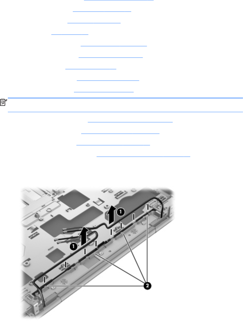
1. Release the wireless antenna cables (1) from the routing channels (2) built into the top cover.
2.
Remove the two Phillips PM2.0×7.6 screws (1) that secure the display assembly to the top cover.
82 Chapter 4 Removal and replacement procedures


