F58F COMMERCIAL DUCT MOUNTED ELECTRONIC AIR CLEANER
68-0141—4
10
M5640A
E
L
E
C
T
R
O
N
IC
A
IR
C
L
E
A
N
E
R
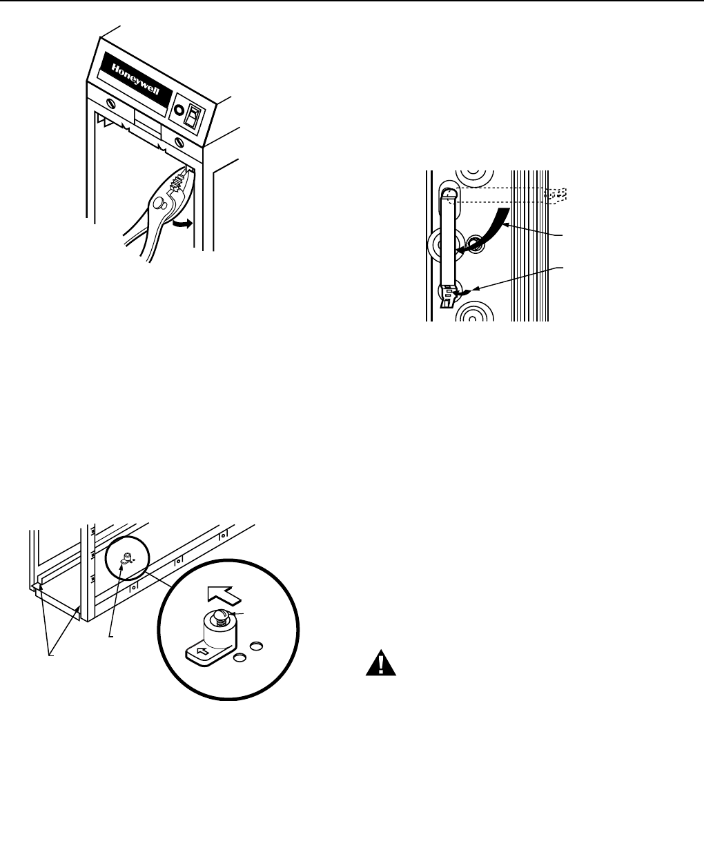
Fig. 14. Crimping prefilter guide.
Position Cell Key
The electronic cell must always be installed so the ionizer
section is on the upstream side. A factory-installed cell key on
the bottom of the cabinet allows the cell to be inserted in only
one direction. If the arrow molded into the plastic key points in
the same direction as the airflow, the ionizer will always be on
the upstream side.
If the position of the key must be reversed, proceed as
follows:
1. Remove the electronic cell.
2. Remove the screw holding the cell key in place. See
Fig. 15.
PREFILTER GUIDES
CELL KEY
M5639
CELL
KEY
ALTERNATE
HOLES FOR
KEY
CELL KEY
SCREW
DOWNSTREAM
AIRFLOW
Fig. 15. Position of cell key determines orientation of cell
(arrow on key must point downstream).
3. Turn the key around and place it over the opposite
holes. The tab on the bottom fits into the larger hole,
and the screw fits into the smaller hole. Make sure the
arrow on the key points in the direction of the airflow
(downstream).
4. Tighten the screw into the new hole.
5. Insert the electronic cell. The ionizer section will now be
on the air-entering (upstream) side of the cabinet.
Attach Cell Handles
The cell handles are attached to the packing insert inside the
access door. They must be installed on the end of the cell
closest to the access door. To install:
1. Orient the cell as it will be when installed. The gray
contact board must be up and the airflow arrow
stamped into the cell must point downstream.
2. Hold the handle sideways and insert the solid tab on
the back of the handle into the slot in the cell. Turn the
handle 90 degrees clockwise to align the divided tab
with the square hole. See Fig. 16.
M6047A
ROTATE 90
DEGREES
FOLD TAB
TO LOCK
HANDLE
IN PLACE
INSTALL HANDLE ON END OF CELL
CLOSEST TO ACCESS DOOR.
Fig. 16. Install handle on end of cell closest to access
door.
3. Insert the divided tab into the square hole.
4. Fold up the wedge and insert it into the divided tab to
lock the handle in place. If necessary, press with a blunt
instrument like the end of a pliers.
Reassemble Air Cleaner
❑ Insert the electronic cell with the gray contact board up
and the airflow arrow pointing downstream. If the cell does
not slide easily into the cabinet, check the orientation of
the cell key.
❑ Insert the prefilter on the upstream side of the cabinet in
the guide provided.
❑ Replace the access door. Insert the tab on the bottom of
the door into the slot in the cabinet, then swing it closed
and press into place. The door must be firmly in place or
the air cleaner will not operate.
Complete Wiring
WARNING
Electric Shock Hazard.
Can cause personal injury.
Do not use an extension cord.
• Assure all wiring complies with local codes and
ordinances.
• The line voltage power source must match the voltage
and frequency printed on the label inside the access
door.
• When the system fan comes on the Airflow Switch
(AFS) senses the negative pressure in the duct and
turns the power supply on. If power to the air cleaner is
controlled by another switch the AFS can be disabled
by cutting the humper on the back of the AFS circuit
board. See Fig. 17.
❑ Plug the electronic air cleaner directly into the correct
voltage and frequency outlet. See Fig. 17 for internal
schematic. The air cleaner will operate properly with any
fan when wired with conduit or plugged in.


