© 2003 Hunter Fan Company 41847-01 04/21/2003
99
99
9
FF
FF
F
ii
ii
i
gg
gg
g
urur
urur
ur
e 28 - Ae 28 - A
e 28 - Ae 28 - A
e 28 - A
ss
ss
s
ss
ss
s
ee
ee
e
mbmb
mbmb
mb
linlin
linlin
lin
g tg t
g tg t
g t
hh
hh
h
e lie li
e lie li
e li
gg
gg
g
hh
hh
h
t ft f
t ft f
t f
ii
ii
i
xx
xx
x
tt
tt
t
urur
urur
ur
ee
ee
e
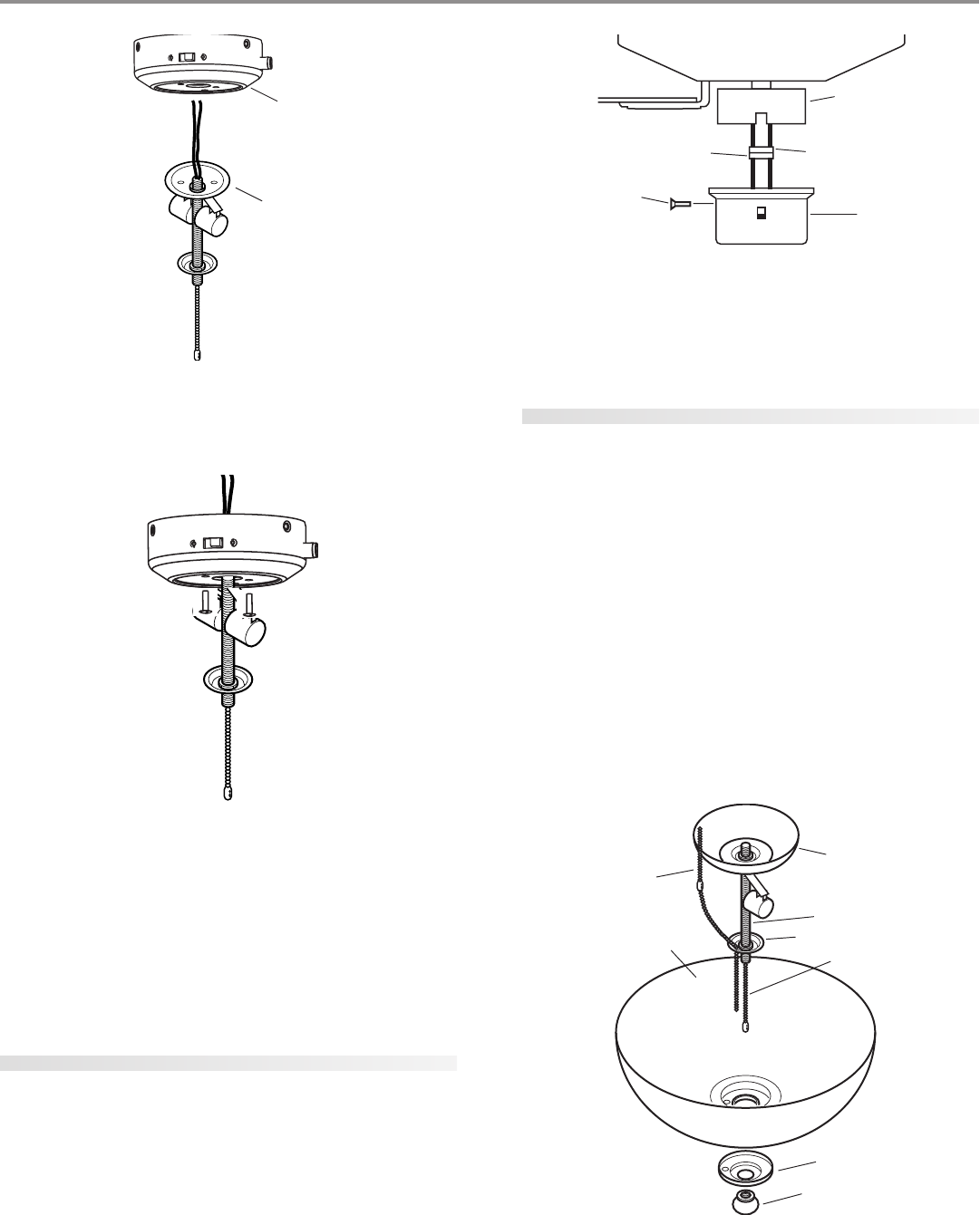
3. Securely tighten the light kit assembly into the bottom of the
lower switch housing. Refer to Figure 29.
FF
FF
F
ii
ii
i
gg
gg
g
urur
urur
ur
e 29 - Ae 29 - A
e 29 - Ae 29 - A
e 29 - A
tt
tt
t
tt
tt
t
aa
aa
a
cc
cc
c
hh
hh
h
ee
ee
e
d lid li
d lid li
d li
gg
gg
g
hh
hh
h
t ft f
t ft f
t f
ii
ii
i
xx
xx
x
tt
tt
t
urur
urur
ur
ee
ee
e
4. Install the nut and washer onto the end of the light kit assem-
bly inside of the lower switch housing. Securely tighten the
nut and washer. Insert and tighten the two #6-32 sems light
fixture mounting screws. Refer to Figure 29.
5. Using the wire nuts on the two light kit wires in the lower switch
housing, connect the black wire from the light kit assembly to
the black/white wire from the lower switch housing and con-
nect the white wire from the light kit assembly to the white
wire from the lower switch housing.
attaching the lower switch housing
1. Connect the upper plug connector from the motor to the lower
plug connector in the lower switch housing assembly. See Fig-
ure 30.
NOTE: Both plug connectors are polarized and will only fit to-
gether one way. Make sure that both connectors are properly
aligned before connecting them together. Incorrect connec-
tion could cause improper operation and damage to the prod-
uct.
FF
FF
F
ii
ii
i
gg
gg
g
urur
urur
ur
e 30 - Ce 30 - C
e 30 - Ce 30 - C
e 30 - C
oo
oo
o
nnnn
nnnn
nn
ee
ee
e
cc
cc
c
tt
tt
t
inin
inin
in
g tg t
g tg t
g t
hh
hh
h
e pe p
e pe p
e p
lulu
lulu
lu
g cg c
g cg c
g c
oo
oo
o
nnnn
nnnn
nn
ee
ee
e
cc
cc
c
tt
tt
t
oo
oo
o
rr
rr
r
ss
ss
s
2. Place the lower switch housing assembly over the upper switch
housing. Align the side screw holes in the upper and lower
switch housings. Attach the lower switch housing to the up-
per switch housing with three #6-32 x 3/8" housing assembly
screws. See Figure 30.
installing the glass bowl
Refer to Figure 31.
1. Install two max 60 Watt medium base incandescent bulbs.
2. Attach the extra pull chain (included in the sack parts) to the
fan pull chain using the plastic breakaway connector.
3. Thread the fan pull chain through the hole in the metal disk.
Then, thread the fan pull chain through the small hole beside
the hole in the center of the glass bowl.
4. Thread the light pull chain through the hole in the center of
the glass bowl.
5. Place the cover plate up against the glass bowl. Align the holes
in the cover plate and glass bowl.
6. Thread the fan pull chain and light pull chain through the ap-
propriate holes.
7. Thread the light pull chain through the finial and screw the
finial onto the threaded rod end until tight.
FF
FF
F
ii
ii
i
gg
gg
g
urur
urur
ur
e 31 - Ie 31 - I
e 31 - Ie 31 - I
e 31 - I
nn
nn
n
ss
ss
s
tt
tt
t
aa
aa
a
llinllin
llinllin
llin
g tg t
g tg t
g t
hh
hh
h
e ge g
e ge g
e g
ll
ll
l
aa
aa
a
ss
ss
s
s bs b
s bs b
s b
oo
oo
o
ww
ww
w
ll
ll
l
Lower Switch
Housing
Light Fixture
Lower Plug
Connector
Upper Switch
Housing
Upper Plug
Connector
Lower
Switch
Housing
Housing
Assembly
Screw
Lower Switch
Housing
Glass Bowl
Fan Pull Chain
Light Pull Chain
Threaded Rod
Cover Plate
Finial
Metal Disk


