21
Maintenance and Basic Service
section 6
MAINTENANCE AND BASIC SERVICE
The MAC 500/E operates under challenging conditions presented by heat, humidity, dust, and touring. It requires reg-
ular cleaning and lubrication to keep performing at its peak. The maintenance schedule will depend heavily on the
application and should be discussed with your Martin technician. This section describes basic maintenance. Refer any
service procedure not described here to a qualified technician.
IMPORTANT!
Excessive dust, grease, and smoke fluid buildup degrades performance and
causes overheating and damage to the fixture that is not covered by the war-
ranty. If you do not feel completely competent to perform the service, consult
qualified service personnel.
Accessing parts
WARNING!
Disconnect the fixture from AC power before removing any cover.
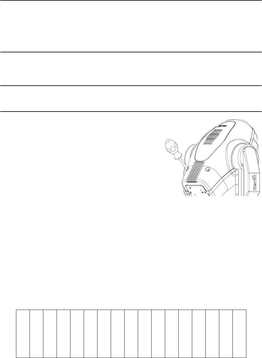
Opening the head
1. Disconnect the fixture from AC power and allow it to
cool.
2. Remove the top shell (look at the label on the back of
the head to see which side is the top) by turning the
2 fasteners 1/4 turn counterclockwise with a large
screwdriver, and lift off the shell.
Opening the base
To access base components, remove the 2 cover plates from the top
of the base. Each plate is fastened with 4 screws. 'RQRWUHPRYHWKHFXUYHGSODWHVIURPWKHVLGHRIWKHEDVH
Removing the printed circuit board
1. Disconnect the fixture from AC power. Remove the cover plate from the front of the fixture.
2. Unplug the white plastic wire connectors from the top of the printed circuit board. To unplug a
connector, hold the plastic connector - never pull the wires - and pull it straight off the pins.
3. Grasp the black pins on either end of the circuit board and gently pull it out. You may have to
guide some wires past the motor housing. Be careful not to knock the copper heat sinks.
4. To replace the circuit board, gently put it back in the base. You may have to guide some wires
past the motor housing. Push the black pins down to lock the board in place.
5. Reconnect the wire connectors. The connectors are labelled on the side that faces up, away
from the ICs. The connection order is:
6. Replace the cover before applying power.
PL551: TILT
PL531: PAN
PL521: DIM
PL511: COL2
PL501: COL1
PL441: ROGO
PL431: GOBO1
PL421: IRIS
PL411: FOCUS
PL401: ROPRI
PL701: PRISM
PL301: GOBO2
PL304: 2-pin fan
PL303: FAN
PL203: OPTO2
PL202: OPTO1
PL201: display


