22
22
COMPONENT
480i/ 480P/ 1080i
AUDIO-
RIGHT
LEFT /
(MONO)
AUDIO-
DT V
(YPbPr/ GBRHV)
MONITOR
IN PU T
OUT
2
1
ANT-A
ANT-B
LOOP
OUT
480i / 480P /1080i
AUD IO-
RI GHT
AUD IO-
LE FT /
(MONO)
V ID EO
S-VIDEO
2
IR EMITTER REPEATER
Y
P r
P b
V
H
Y
G
Pb
B
P r
R
Other A/V Device
1
Ferrite
Core
A/V Receiver
IR EMITTER REPEATER
TV back panel (Detailed View)
D IG ITA L
SURROU ND
S
CH
D IG ITA L
SURROU ND
S
AH
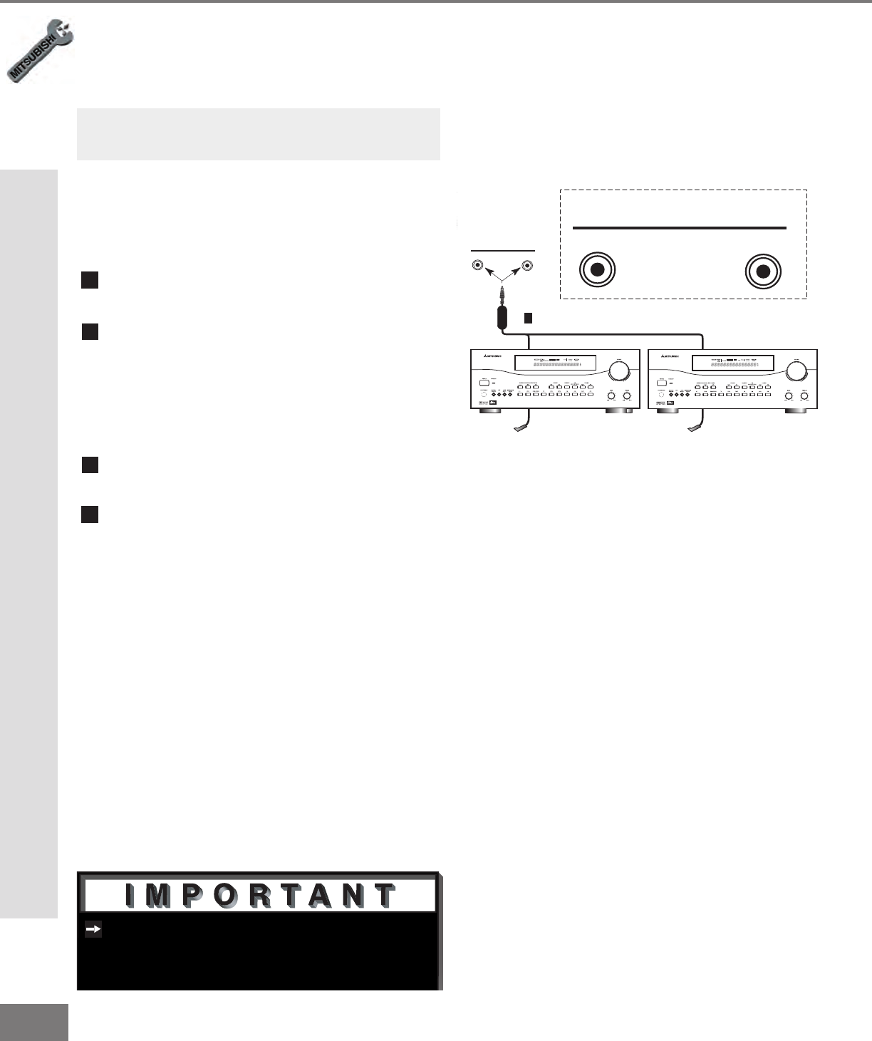
Figure 1. Connecting the System 4 Home Theater IR
Control.
See page 57 for details on using the
TV’s IR emitter to control a Mitsubishi
A/V receiver.
Connect the IR emitter to IR EMITTER
REPEATER on the TV back panel.
Place the IR emitter cable under or
along the side of the A/V device. Place
the IR lens directly in front of the A/V
device infrared signal receiver. Infrared
signal receivers are usually behind the front
translucent panel of the receiver.
Place the unused transmitter in an out-of-
the-way location.
For permanent installation of the IR emitter
cable, use the included adhesive tape to
secure the bottom of the emitter to the
anchoring object of your choice.
Connecting the System 4 Home Theater IR Control
(Applicable for WS-55411, WS-65411 and WS-73411 models only)
(Figure 1)
Connecting the System 4 Home Theater IR Control
Connecting the System 4 Home
Theater IR Control.
Note: The TV back panel and connections
shown here are for reference only and may
vary by model.
