Model 2350 / 2360 Gas Monitor (3/99)
Page:
2.0 INSTALLATION
2.1 UNPACKING AND INSPECTION
Remove the gas monitor from its packing container and inspect to insure that all items listed on the packing slip
have been received in good condition.
2.2 INSTALLATION AND SET-UP
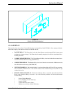
2.2.1. ENCLOSURE MOUNTING
Install a three position gang box (not supplied) on a vertical surface in the location selected for the gas
monitor. Entry for power supply wiring and for alarm contacts should be supplied through conduit connected
to the knock out.
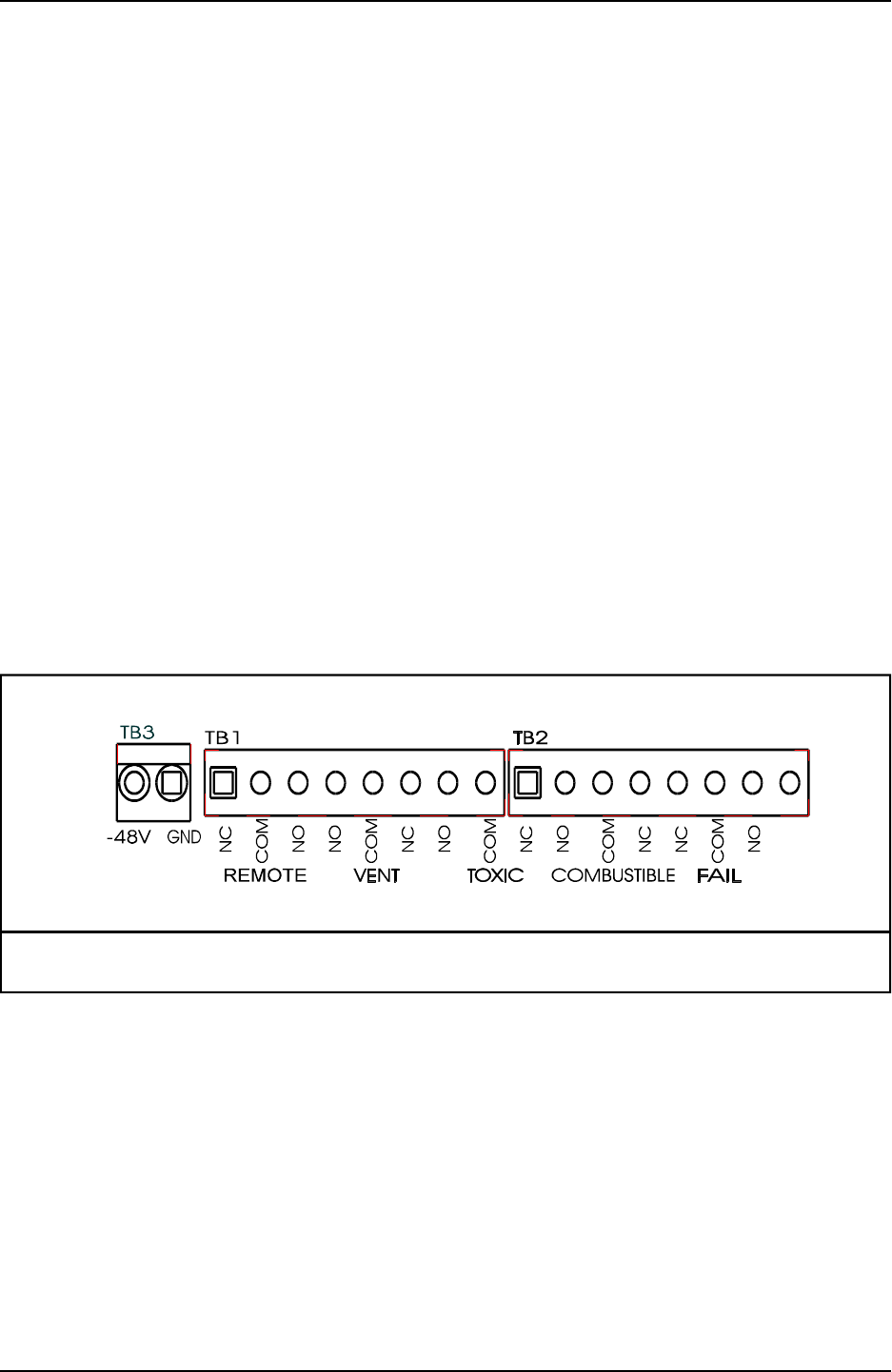
2.2.2. INTERFACE WIRING
D.C. POWER: Pull -48 VDC wiring into the gang box, allow 10” of service loop and strip 1/8” of insulation
to prepare for connection to the monitor.
ALARM RELAYS: Pull any required alarm relay wiring into the gang box, allow 10” of service loop and
strip 1/8” of insulation for connection to the monitor.
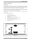
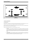
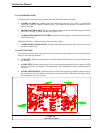
WIRING CONNECTIONS: Using Figure 2.1 as a guide, connect the -48 VDC wiring and the alarm relay
wiring to the appropriate terminal points. Open the terminals by turning the locking screw counterclockwise,
insert the wire so that the full 1/8” strip is inside the connector and close the connector securely by turning the
screw clockwise.
2.2.3. START-UP
POWER ON: Apply power to the -48 VDC wiring. After a short pause the audible alarm will sound and the
alarm lights will light on the front panel. The alarms will stabilize within five minutes at which time the
audible will cease and the “safe” lights on the front panel will light.
MONITOR STABILIZATION: During the first 24 hours of operation the sensors may be unstable and
alarms may occur. Alarms should be ignored during this period and remote annunciation should not be
activated.
Figure 2.1
Interface Wiring Terminal Positions
5