22
ASSEMBLY
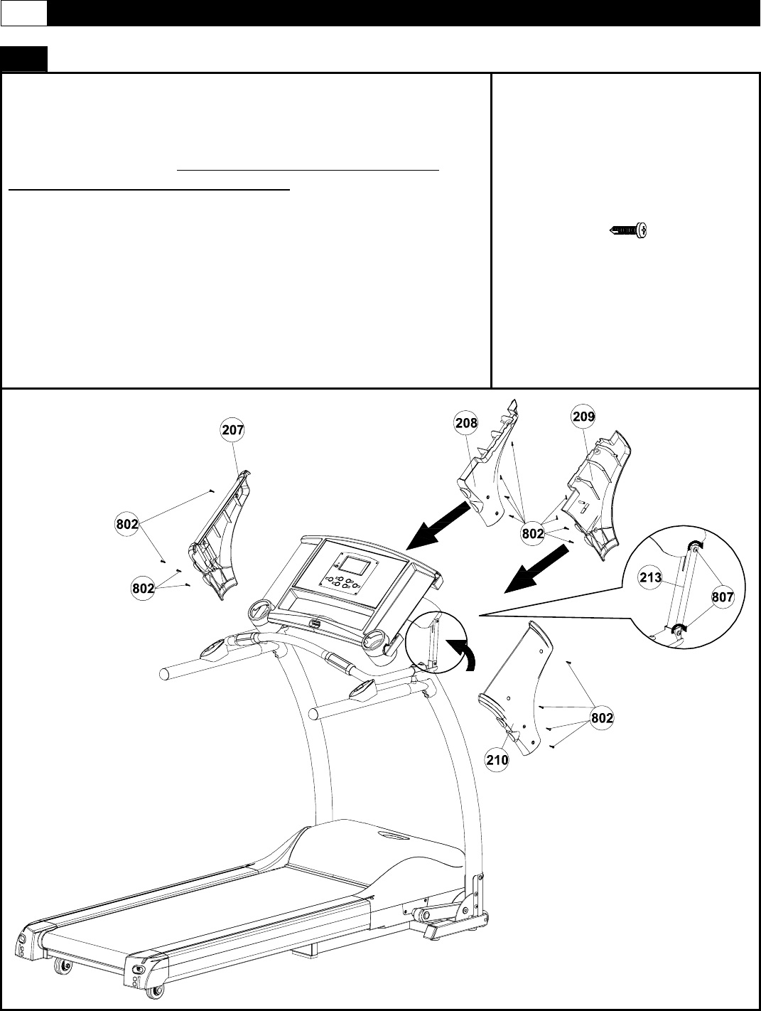
STEP 5: Assemble Computer Console
A) Rotate the console until it stops as shown in diagram
below .
B) Tighten the screw (807) of the console connect tube (213)
for right and left side . Console connect tube (213) will be
adjust for the next steps of assembly .
C) Attach the Handle Bar Cover - LR (208) to the underside of
the console and the inside of the left upright (301), Secure with
four M4×15mm screw (802). And secure with two M4×15mm
screw (802) between the Handle Bar Cover - LR (208) outside
and the console housing -upper.
D)Attach the Handle Bar Cover - LL (207) to the top of the
console and the outside of the Upright - Left (301).And secure
with four M4×15mm screw (802).
E) Repeat the above process for the right hand side cover
(209) and cover (210) as shown in diagram.
802
X20


