FIGURE 3
FIGURE 4
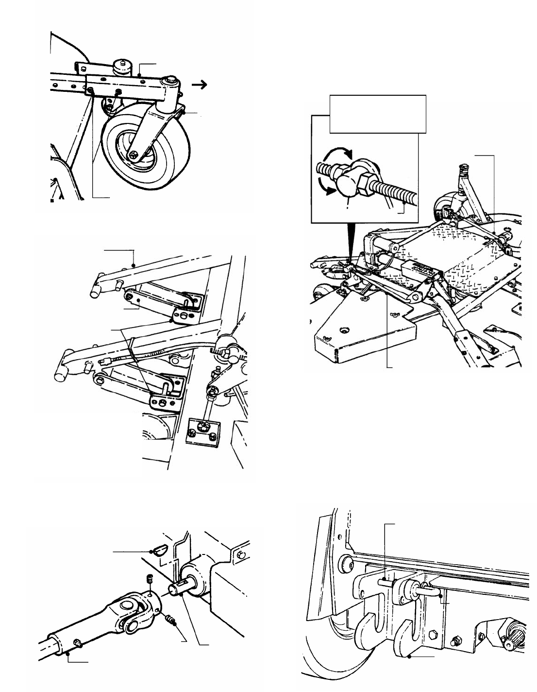
FIGURE 5
STEP 7: Secure Transfer Shaft to Gear Box Shaft
using two screws. See Figure 5. Tighten securely.
STEP 8: Place a 2x4 under each rear caster. Block the
front caster wheels so that they will not roll.
STEP 9: Locate jam nuts on the right timing rod and
the right rear deck hanger rod. See Figures 6 and 12.
Note position of nuts. You must return both nuts to this
position after attaching the deck.
FIGURE 6
STEP 10: Run each (2) jam nut up against the swivels
on the timing rod and the hanger rod. The deck linkage
will not float when the nuts are in this position. This will
allow the use of the electric actuator on the deck to lift
and attach the deck frame to the power unit.
STEP 11: Located on the hitch plates at the front of the
Power Unit, rotate the Spring-Loaded Hitch Latch Pins to
the unlatched position. See Figure 7.
STEP 12: Engage Parking Brake. Start Power Unit.
FIGURE 7
2) EXTEND CASTER OUT TO LAST SET OF
HOLES.
3) REINSTALL HARDWARE.
SUPPORT ARM
FWD
ASSEMBLY
HARDWARE
DECK FRAME
HOLE
DECK SIZE IDENTIFICATION
NUMBERS STAMPED INTO ITS
SIDE. PIN LOCATION IN
CORRECT HOLE SHOULD
CORRESPOND WITH DECK SIZE.
(1/4 X 7/8)
SHAFT
SET SCREWS
LATCH
PIN
UP TO UNLATCH
POSITION
POSITION
PLATE
ROD
TIMING ROD
TIGHTENED
AGAINST SWIVEL


