9.2 Disassembly and Assembly
9.2.1 Removal of Housing Components/Covers
9.2.1.1 Cover for Electrical Connection
Dependent on the type of installation the cable loom
exits the air heater either on the left or right.
The cover (1, Fig. 901) may be levered off using a blunt
blade in the areas marked
X .
9.2.1.2 Grates for Heating Air Inlet and Outlet
The grates (5, Fig. 901) can be released from the
covers by twisting and pulling off forwards.
9.2.1.3 Covers for Heating Air Inlet and Outlet
Both covers (3 and 6, Fig. 901) can be released and
removed by pressing the four detents on top and bottom
using a suitable tool.
9.2.1.4 Upper Housing Shell
NOTE
The covers for the heating air inlet and outlet must be
removed.
The upper shell (2, Fig. 901) can be raised by pulling up.
Y
9.2.1.5 Lower Housing Shell
902
9 Repair
Air Top 2000 S
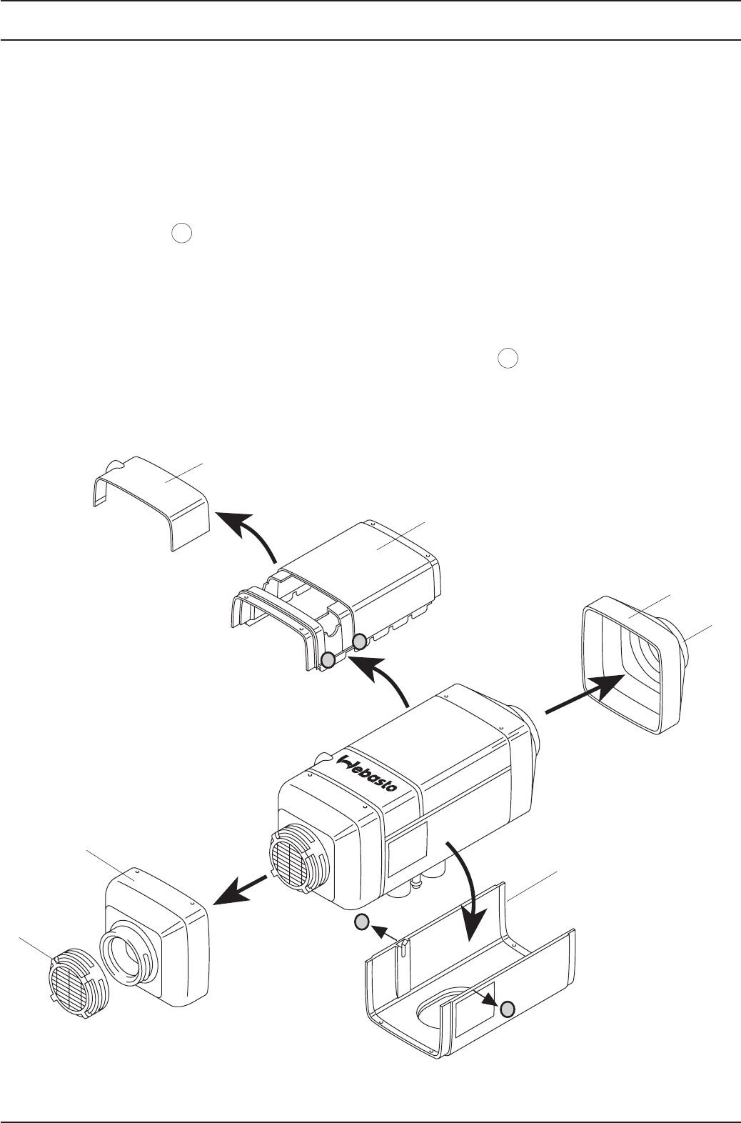
Fig. 901 Removal of Housing Components/Covers
X
X
Y
Y
1
2
3
4
5
6
1 Cover, Electrical Connection
2 Upper Housing Shell
3 Cover, Heating Air Outlet
4 Lower Housing Shell
5 Grates
6 Cover, Heating Air Inlet
5
By gently pulling the lower shell (4, Fig. 901) on both
sides in the areas , you can release the fixing and
the shell can be taken off the motor casing.


