Thermo 90 S / Thermo 90 ST 8 Service work
807
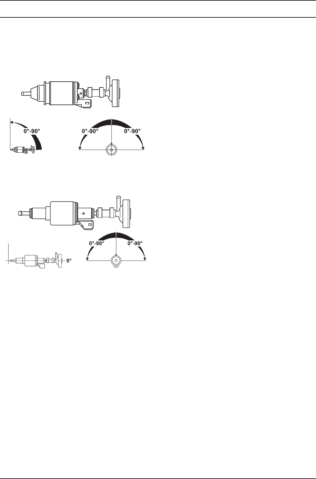
8.6.3 Metering pump with damper
The metering pump is a combined delivery, metering and
shut-off system and is subject to certain installation
criteria (Figs. 802 and 808).
12 volts and 24 volts – petrol and diesel DP2
12 volts and 24 volts – diesel DP 30.2 only
Horizontal installation position
Fig. 808 Metering pump, installation position and
attachment
8.6.3.1 Installation position
Before installing the metering pump, ensure that the
maximum pressure occurring at the pickup point is less
than 0.2 bar
It is advisable to install the metering pump in a cool place.
The maximum ambient temperature must not exceed
+20 °C for petrol and +40 °C for diesel at any time during
operation.
The metering pump and fuel lines must not be installed
within range of the radiated heat from hot vehicle parts.
A heat shield must be used if necessary.
The pump should ideally be installed near the tank.
8.6.3.2 Installation and attachment
The metering pump must be secured with a vibration-
damping mounting. Its installation position is limited as
shown in Fig. 808 in order to ensure effective automatic
bleeding.
8.6.4 Fuel filter
Only a Webasto filter, order no. 487 171, is allowed to be
used if the fuel is expected to be contaminated. Install
vertically if possible, however at least horizontally.
NOTE
Note the installation position and direction of flow.
8.6.5 Combustion air supply
Under no circumstances may the combustion air be taken
from areas occupied by people. The combustion air intake
opening must not point in the direction of travel. It must be
located so that it cannot become clogged with dirt or snow
and cannot suck in splashing water.
The combustion air intake line (internal diameter at least
30 mm) may be 0.5 m to 5 m long with several bends
totalling 360°. Minimum bending radius is 45 mm.
The combustion air inlet must not be routed above the
exhaust outlet.
NOTE
If the combustion air intake line cannot be installed so that
it slopes downwards, a water drain hole (with a diameter
of 4 mm) is to be made at its lowest point.
If the heater is installed in a general installation space
near the vehicle’s fuel tank, the combustion air must be
taken in from the outside and the exhaust fumes
discharged into the atmosphere. The openings must be
splash-proof.
A ventilation opening measuring at least 6 cm
2
is required
if the heater is installed in an enclosed box. The size of the
ventilation opening must be increased accordingly if the
temperature in the box exceeds the permitted ambient
temperature of the heater (see Technical data).


