


WARNING: Installation and removal of the Module must
be carried out by qualified personnel only. Before
installing the Module into a unit, you must first
disconnect the unit from the mains power supply. For
full safety instructions, refer to the user guide that
accompanies the unit.
AVERTISSEMENT: Confiez l'installation et la dépose de
ce Module à un personnel qualifié. Avant d'installer ce
Module dans un groupe, vous devez au préalable
débrancher ce groupe de l'alimentation secteur. Pour
prendre connaissance des consignes complètes de
sécurité, consultez le guide utilisateur qui accompagne
ce groupe.
WARNHINWEIS: Die Installation und der Ausbau des
Moduls darf nur durch Fachpersonal erfolgen. Vor dem
Installieren des Moduls in einem Gerät muß zuerst der
Netzstecker des Geräts abgezogen werden. Vollständige
Sicherheitsanweisungen sind dem Benutzerhandbuch des
Geräts zu entnehmen.
WARNING: When the Module is inserted into the
switch, the captive screws securing the Module must be
tightened with a suitable tool. Keep the blanking plate
and the fixings in a safe place. If you remove the
Module at any time, you must then replace the blanking
plate.
AVERTISSEMENT: Quand le Module est inséré dans le
commutateur, visser le module, en le securisant
fortemant avec un outil adapté. Conservez la plaque
d'obturation et les fixations en lieu sûr. Si vous retirez le
Module à tout instant, vous devez alors replacer la
plaque d'obturation.
WARNHINWEIS: Beim Einsetzen des Moduls in dem
Switch sind die unverlierbaren Schrauben mit einem
passenden Werkzeug festzuziehen. Die Distanzplatte und
die Befestigungselemente an einem sicheren Ort
aufbewahren. Beim Austausch des Moduls ist auch die
Distanzplatte zu ersetzen.
WARNING: RJ-45 Ports. These are shielded RJ-45 data
sockets. They cannot be used as standard traditional
telephone sockets, or to connect the unit to a traditional
PBX or public telephone network. Only connect RJ-45
data connectors, network telephony systems, or network
telephones to these sockets.
Either shielded or unshielded data cables with shielded
or unshielded jackets can be connected to these data
sockets.
AVERTISSEMENT: Points d’accès RJ-45. Ceux-ci sont
protégés par des prises de données. Ils ne peuvent pas
être utilisés comme prises de téléphone conventionnelles
standard, ni pour la connection de l’unité à un réseau
téléphonique central privé ou public. Raccorder
seulement connecteurs de données RJ-45, systèmes de
réseaux de téléphonie ou téléphones de réseaux à ces
prises.
Il est possible de raccorder des câbles protégés ou non
protégés avec des jacks protégés ou non protégés à ces
prises de don
WARNHINWEIS: RJ-45-Porte. Diese Porte sind
geschützte Datensteckdosen. Sie dürfen weder wie
normale traditionelle Telefonsteckdosen noch für die
Verbindung der Einheit mit einem traditionellem
privatem oder öffentlichem Telefonnetzwerk gebraucht
werden. Nur RJ-45-Datenanscluße, Telefonnetzsysteme
or Netztelefone an diese Steckdosen anschließen.
Entweder geschützte oder ungeschützte Buchsen dürfen
an diese Datensteckdosen angeschlossen werden.
Handling the Module
The Module can be easily damaged by electrostatic
discharge. To prevent damage, observe the following:
Always wear an anti-static wristband connected to a
suitable earth point.
Do not remove the Module from its packaging until
you are ready to install it into a Switch.
Do not touch any of the pins, connections or
components on the Module.
Handle the Module only by its edges and front panel.
Always store or transport the Module in anti-static
packaging.
Installing the Module into a Switch
CAUTION: This Module is not hot-swappable. Always
make sure that the Switch is powered down and
disconnected from the mains before installing or
removing a Module. Use the following instructions when
installing or removing a Module.
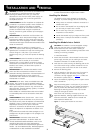
To install the Module:
1
Ensure that the Switch is disconnected from the mains
power supply and that you are wearing an anti-static
wristband connected to a suitable earth point.
2
Undo the two screws securing the blanking plate at the
rear of the Switch using a suitable screwdriver. Do not
remove any other screws from the rear of the Switch.
3
Remove the blanking plate.
4
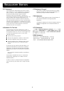
Hold the Module so that the text on the front panel is
upright and insert it into the Switch, ensuring the
connectors are fully engaged (see Figure 1
). Make sure
the Module is pushed fully in.
5
Secure the Module by tightening the two captive screws
with a screwdriver.
Keep the blanking plate in a safe place. If you remove
the Module at any time, you must replace the blanking
plate to prevent dust and debris entering the Switch.
Replacing the blanking plate will also help circulate
cooling air through the Switch.
Each Switch has the facility to accept up to two
Expansion Modules, allowing Gigabit Ethernet or Fast
Ethernet connections. Modules can be inserted into
either Expansion Module slot.
Figure 1
Inserting the Module into the Switch
I
NSTALLATION
AND
R
EMOVAL
2