Activating the Module
1
Ensure that the Switch is powered-up.
2
Plug the RJ-45 connector on the Category 5 cable into
the RJ-45 port on the Module.
3
Connect the other end of the Category 5 cable to a
device that supports 1000BASE-T.
4
Check the LEDs on the front of the Switch to ensure
that the Module is operating correctly. Refer to “
LEDs”
for more information.
Removing the Module from a Switch
1
Ensure that the power supply and the backbone
connection cables are disconnected from the Switch.
2
Undo the Module’s two captive screws with a suitable
screwdriver. Do not remove any other screws from the
Switch.
3
Remove the Module.
4
If you are not fitting another Module immediately, you
must replace the blanking plate to ensure that dust and
debris do not enter the Switch. Replacing the blanking
plate will also help circulate cooling air through the
Switch.
When the Module is installed, you can configure it
through your Switch to add extra functionality. Refer to
the documentation that accompanies your Switch 4300
for more information.
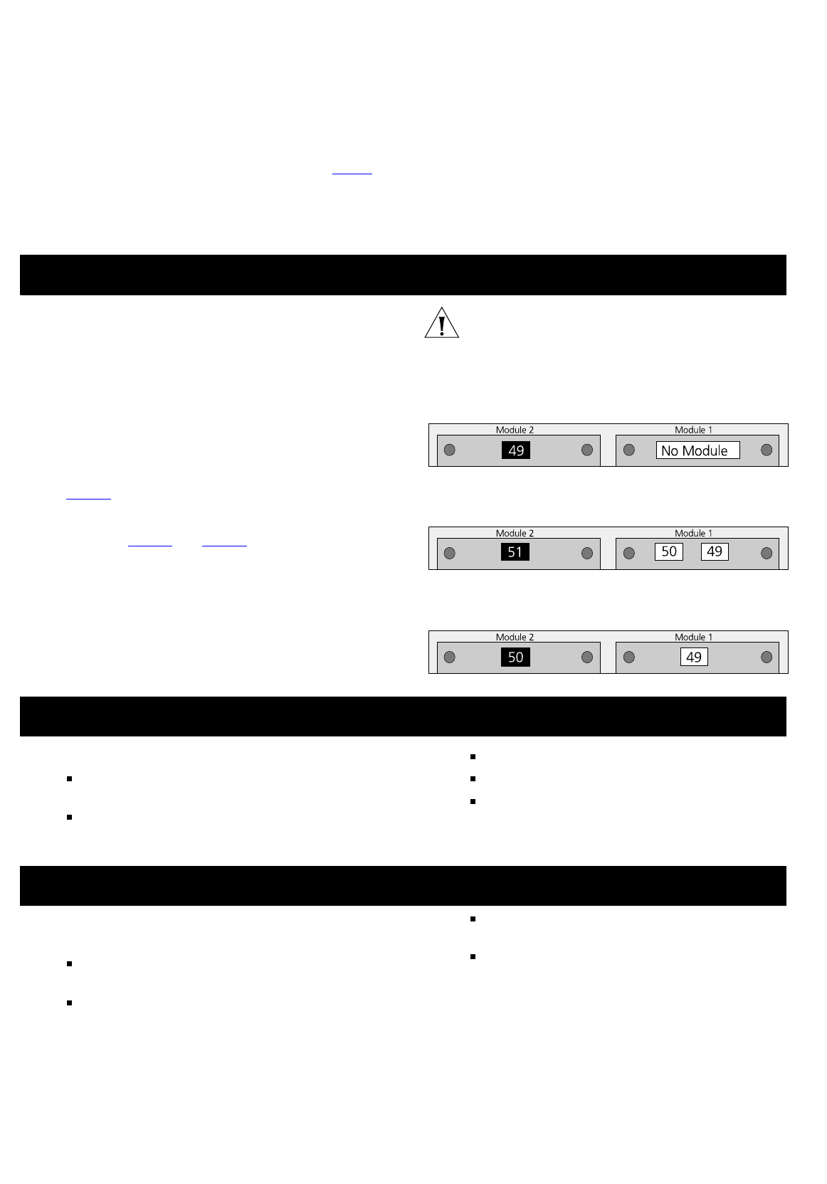
The Switch 4300 dynamically assigns port numbers to
each Module installed, so if you add, replace or remove
a Module, the port number of the other Module may
change. The port numbers allocated depend on the type
of Module; the number of Modules installed and the
slots into which they are fitted.
Figure 2
shows how a single port Module, inserted into
Slot 2, will be assigned a port number of 49. If you then
insert an additional dual or a single port Module into
Slot 1 (see Figure 3
and Figure 4) the port numbering
will change. The port number originally assigned to the
Module in Slot 2 (and any port parameters you may
have set against that port number) will be re-assigned to
the Module installed into Slot 1. Similarly, if you then
remove the Module from Slot 1, the port number and
parameter settings will be re-assigned to the Module in
Slot 2.
CAUTION: Always check that each port number has the
correct parameter settings after adding, changing or
removing a Module. This is due to the method in which
the Switch dynamically assigns port numbers.
Figure 2
Rear View of Switch 4300
Module Port Number Allocation
Figure 3
Rear View of Switch 4300
Installing a Dual Port Module into Slot 1
Figure 4
Rear View of Switch 4300
Installing a Single Port Module into Slot 1
When using the Module port, note the following:
The Module only operates in full duplex mode for
1000BASE-T.
The Module operates in half and full duplex mode for
10BASE-T and 100BASE-TX.
The Module is not hot-swappable
The Module is not hot-insertable.
The Module only operates with Category 5 Ethernet
cable.
If you suspect a problem, carry out these steps before
contacting your supplier:
Ensure that the Module is correctly installed in the
Switch.
Ensure that the Switch in which the Module is fitted
is powered-up.
Ensure that the device at the far end of the line is
powered-up and operating correctly.
Check that all connectors on the Category 5 cable
are correctly engaged.
For information about technical support , refer to the
documentation supplied with your Supplier.
M
ANAGING
THE
M
ODULE
M
ODULE
P
ORT
R
ESTRICTIONS
P
ROBLEM
S
OLVING
3


