


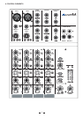
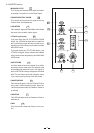
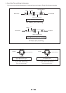
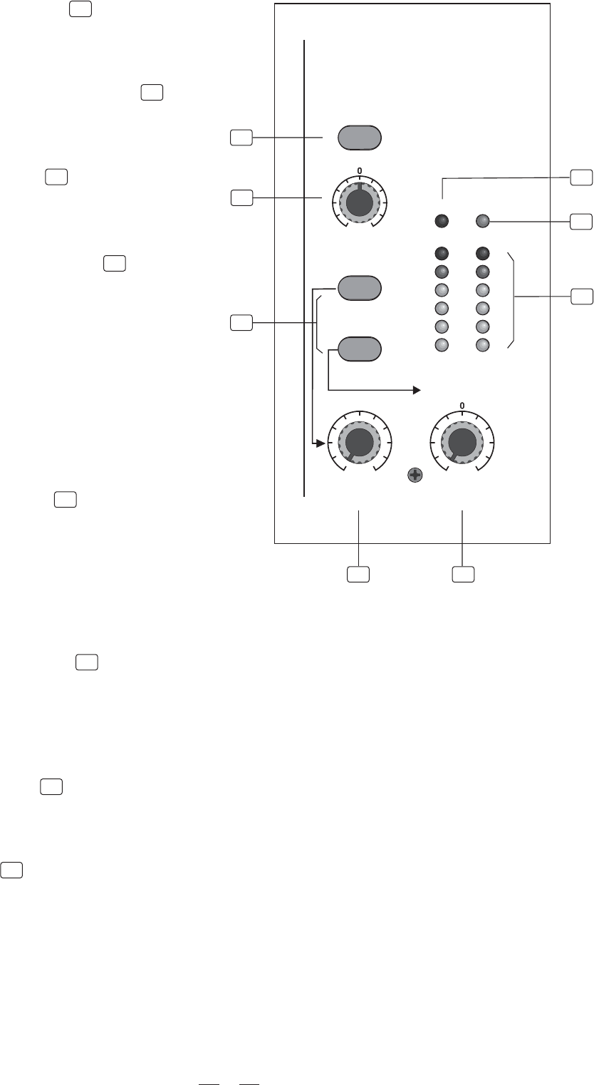
4.9 MASTER section
12
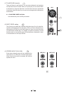
- PHONES/CONTROL ROOM
13
- LED METER
This stereo 6 segments Led Meter will indicate
the level of the overall output signal.
8
11
- MAIN MIX LEVEL
15
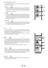
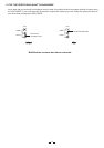
- AUX RETURN
14
- 2 TRACK signal path
16
- PHANTOM PWR
This switch will apply +48 Volt Phantom Power
only to the 2 XLR microphone inputs. Never con
-nect microphones when the Phantom Power is
on already.
18
- PWR
This Led indicates when the Power is on in your
S-6.
- PHANTOM
This LED indicates when the Phantom Power is
switched on.
17
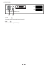
AUX RETURN
-4
-10
-30
0
10
CLIP
PHANTOM PWRPHANTOM PWR
2TK TO
CONTROL ROOM
2TK TO
CONTROL ROOM
2TK TO MIX
OUTPUT LEVEL
L R
-
8
MAX
MAIN MIX
LEVEL
-+15
8
-+15
8
PHANTOM PWR
PHONES /PHONES /
CONTROL
ROOM
CONTROL
ROOM
1112
13
15
17
14
16
18
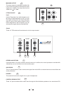
This Control sets the amount of signal sent either
to the Main Out socket or to the Tape Output.
This Control sets the amount of signal sent to the
Control Room and headphone.
If you push down the 2TK TO CONTROL ROOM
button, the 2 TRACK IN signal will be routed into
the Control Room output and the level will be ad-
justed by the Control Room knob nearby the Main
MIX LEVEL knob.
If you push down the 2TR TO MIX button, the
2 TRACK IN signal will be routed into the MAIN
output and will be adjusted by the MAIN MIX
LEVEL knob.
It will be used to return the signal of an effect
processor into the mixer but it can be also used
as an additional stereo line input. This signal of
the AUX RETURN is always assigned to the MAIN
MIX. The Aux Return input will operate in mono
if you connect an input only to the left socket.