


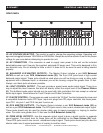

Q-SPAND™ CONTROLS AND FUNCTIONS
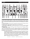
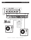
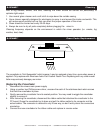
40. REC OUT - This is a low current unbalanced output source designed for various tape and CD
recorders. The Record Out (REC OUT) level is dictated by the Channel Fader Level (9), it is not infl u-
enced by the Master Volume Control (26).
41. CHANNEL 4: LINE 4 RCA INPUT JACKS - These Jacks are used for line level inputs. Connect
CD players or Tape Decks to LINE inputs. Line level musical instruments with stereo outputs such as
Rhythm Machines or Samplers should also be connected to LINE inputs. Turntables should only be
connected to “Phono” inputs. The red colored RCA jack represents the right channel input and the white
represents the left channel input. Input volume will be controlled by channel four Channel Fader (9).
The channel Source Selector Switch (5) must be in the "Line 4" position, to monitor any source con-
nected to these jacks.
42. CHANNEL 3: LINE 3 RCA INPUT JACKS - These Jacks are used for line level inputs. Connect
CD players or Tape Decks to LINE inputs. Line level musical instruments with stereo outputs such as
Rhythm Machines or Samplers should also be connected to LINE inputs. Turntables should only be
connected to “Phono” inputs. The red colored RCA jack represents the right channel input and the white
represents the left channel input. Input volume will be controlled by channel three Channel Fader (9).
The channel Source Selector Switch (5) must be in the "Line 3" position, to monitor any source con-
nected to these jacks.
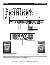
43. CHANNEL 3: PHONO 3 INPUT/AUX 3 JACKS - The type of input must directly refl ect the selected
mode of the Line Level Selector Switch (5). Connect turntables equipped with MM pickup cartridge
to PHONO inputs (All DJ turntable use MM pick-up cartridges). CD players or Tape Decks and other
line level instruments may be connected to these jacks as long as the Line Level Selector Switch
(5) is in the “AUX 3” position. The red colored RCA jack represents the right channel input and the
white represents the left channel input. Input volume will be controlled by channel three Channel Fader
(9). The channel Source Selector Switch (5) must be in the "Phono 3/Aux 3" position, to monitor any
source connected to these jacks.
44. CHANNEL 3 LINE LEVEL SELECTOR SWITCH - This switch is used to change the mode of
Channel 3: Phono 3 Input/Aux 3 Jacks (43). When connecting turntable to the Channel 3: Phono 3
Input/Aux 3 Jacks (43) be sure this switch is in the PHONO position, and when using line level input
devices be sure this switch is in the AUX position. Always be sure main power is shut off before change
the position of the Line Level Selector Switch.
45. CHANNEL 2: LINE 2 RCA INPUT JACKS - These Jacks are used for line level inputs. Connect
CD players or Tape Decks to LINE inputs. Line level musical instruments with stereo outputs such as
Rhythm Machines or Samplers should also be connected to LINE inputs. Turntables should only be
connected to “Phono” inputs. The red colored RCA jack represents the right channel input and the white
represents the left channel input. Input volume will be controlled by channel two Channel Fader (9).
The channel Source Selector Switch (5) must be in the "Line 2" position, to monitor any source con-
nected to these jacks.
46. CHANNEL 2: PHONO 2 INPUT/AUX 2 JACKS - The type of input must directly refl ect the selected
mode of the Line Level Selector Switch (5). Connect turntables equipped with MM pickup cartridge
to PHONO inputs (All DJ turntable use MM pick-up cartridges). CD players or Tape Decks and other
line level instruments may be connected to these jacks as long as the Line Level Selector Switch
(5) is in the “AUX 2” position. The red colored RCA jack represents the right channel input and the
white represents the left channel input. Input volume will be controlled by channel two Channel Fader
(9). The channel Source Selector Switch (5) must be in the "Phono 2/Aux 2" position, to monitor any
source connected to these jacks.
©American Audio® - www.americandj.com - Q-SPAND™ Instruction Manual Page 10