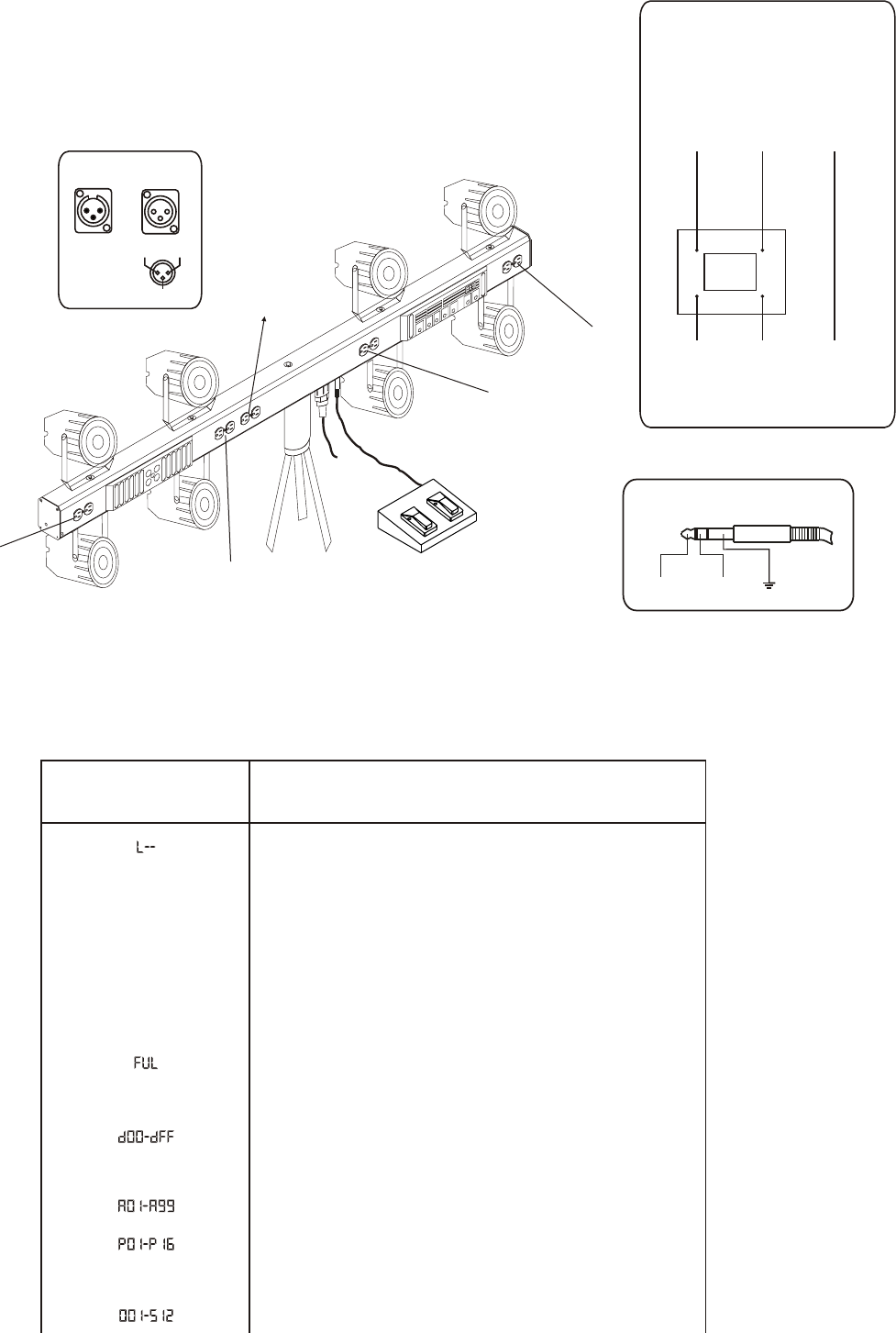
The indications in DISPLAY and explanations
APPENDIX II
APPENDIX I
TO ESTABLISH PROPER CONNECTION CONFIGURATION,
PLEASE REFER TO THE RIGHT ILLUSTRATION:
1=Ground
2=Data-
3=Data+
12
3
DMX IN DMX OUT
1/4"stereo jack
FULL ON
STAND BY
NOTE: USE RECOMMEND SCREW ONLY.
(Dimension: M10x25mm)
POWER
uncontrolled
R-2(Foot Controller)
by 1/4" stereo jack
CH1
CH2
CH3
CH4
DMX address 1-512
E00-E25
Preset minimum dimming level of 0-25%
Program 1-16
Speed with the range of 1/60-20 step per second
F00-F99
Fade time with the range of 0-10 seconds
0-100% dimming level
STD
STAND BY
FULL ON
IN
DMX input
OUT
DMX output
CRO
Only FULL ON and STAND BY enabled, dimming disabled
NOR
Output 0-100% dimming enabled
R--
Data information of CH1-4 corresponding to CH4-1 output
Data information of CH1-4 corresponding to CH1-4 output
INDICATION
EXPLANATION
L N E
L N E
Circuit
Breaker
20A
black
white green
AC POWER OUTLET
Additional note:
To prevent current over 20A,
a external circuit breaker is
recommended to be used.
Connect to
the apparatus


