


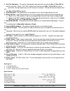

1. Power Switch - Applies main power to the unit
2. Audio Control - This knob controls the audio sensitivity the unit will react to.
3. Chase Speed Control - Two sperate knobs to control independent chase speed for channels 1-4
and channels 5-8.
4. Latch Buttons - Pressing these buttons will maintain power to the fixture connected to the
corresponding channel.
5. Channel Indicators - These LED’s will glow indicating channel activity.
6. Stand-By Indicator - This LED will glow indicating controller is in Stand-By mode.
7. Chase Audio Selector - These 3 position switches control the chase modes for channels 1-4
(Bank 1) and channels 5-8 (Bank 2). The two banks can be controllers independently.
a. When the switch is in the “10MIN” position (Up) the chase speed will react more slowly.
b. When the switch is in the “x 1” position (Center) the chase speed will react more quickly.
c. When the switch is in the “Audio” position (Lower) the chase will react to audio sensitivity.
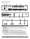
CONTROL OUTPUT
DC IN
+9V~+12V
200MA MIN.
AUDIO IN
FOOT CONTROL
PIN
CH
5
VCC
9876543
4
21
32 1 8 7 6
OUTPUT INPUT CIRCUIT BREAKER AC POWER
AC 120~60Hz,15A
American DJ Supply
®
Los Angeles Ca. Light Copilot Page 2
Controller - Rear Panel
Relay Pack - Side View
Controls and Functions:
13 14 15 16
20191817
American DJ®
POWER
AUDIO
SPEED SPEED
STAND BY
CH1-4
CH5-8
1 5
11
10
9
8
7
64
3
2
1
12
Controller - Front Panel