


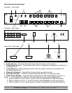

8. Full On Switches - This switch is designed to be used with the optional Bar-T-Cue/FS foot
switch controller. When in the “ON” position and used with the Bar-T-Cue/FS foot switch
controller, the foot switch can turn all fixture on in a bank. This switch has no function with-
out
the Bar-T-Cue/FS foot switch.
9. Flash Buttons - Use these button to momentarily turn the corresponding fixture on.
10. Effect Switch - Use these switches to link the corresponding channels the the chase settings.
a. When in the “ON” position (Top) the corresponding fixture will be linked to chase modes.
b. When in the “OFF” position (Lower) the corresponding channel will react only to the Latch
Buttons (Fig.4) and Flash Buttons (Fig.9).
11. Stand-By Switch - This switch will hold all output to all channels when depressed. It’s func-
tion
is indicated by the Stand-By Indicator (Fig.6).
12. Internal Microphone - This picks an audio signal to run the audio chase.
13. Control Output - This connection is used to connect a 9 pin com cable from the controller to
the
relay pack. Be sure to only use the LC-25 cable that comes with your unit, this cable is especial-
ly
designed to be used with your Light Copilot.
14. DC Input - Used to plug in an external power supply (9v~12v DC) - Typically not used under
normal conditions.
15. Audio Input - Used in audio chase mode - Use to connecting an external audio source directly
to the unit. This will provide a more accurate audio source when the internal mic is not
sensitive enough or when the unit is mounted far away from an audio source (speaker).
16. Foot Control Input - This connection is used to connect a Bar-T-Cue/FS foot switch controller
to the unit via a 1/4” stereo jack.
17. Signal Output - This 9 pin com connection is used to connect another LC-8SP relay pack to the
controller unit. Be sure to use only specified American DJ 9 pin com cables.
18. Signal Input - Used to link the controller unit with LC-8SP relay pack via a specified 9 pin com
cable.
19. Circuit Breaker - A built in 15A circuit breaker designed to protect wiring under heavy or over-
loaded conditions.
20.Power Input - AC 120v~60Hz, 15A - This will also power the controller unit through the 9 pin
com cable.
Packing List:
1. 1) LC-100 controller
2. 1) LC-8SP - Switch pack
3. 1) LC-25 - 25 foot 9 pin com extension cable
Specifications:
Power Input LC -100........................................................................................DC +9 ~ 12v, 200mA min.
Power Input LC -8SP................................................................................................AC 120v ~ 60Hz, 15A
Channel Output......................................................................................10A per channel, Total 15A max.
Circuit Breaker.......................................................................................................................................15A
LC-100 Dimensions..........................................................................................1 3/16”h x 19”w x 2 7/16”d
LC-8SP Dimensions..........................................................................................................4”h x 19”w x 4”d
Total Weight (System).............................................................................................................7lbs / 3.5Kg
American DJ Supply® Los Angeles Ca. Light Copilot Page 3