


SVT-GS Gene Simmons Punisher
4
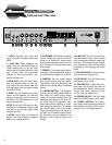
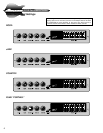
The Front Panel Controls and Their Use
4 5 6 7 8 103 12 13 14 1521 9 11
1. INPUT: Connect your bass here
using a standard shielded instrument
cable.
2. 15dB PAD: When engaged, this
switch cuts the input signal level by
15dB, allowing you to set the Gain
control (#4) for the best signal to noise
ratio. (If your bass has high-output
pickups or active electronics, you
should use the Pad.)
3. PEAK LED: This LED lights when-
ever any preamp stage is near clip-
ping. Adjust the Gain control (#4) until
a strong signal from your bass causes
this LED to flicker.
4. GAIN: This serves as the input level
control for the amplifier. For the best
signal to noise ratio, set this control so
the Peak LED (#3) flashes when you
hit your strings hard.
NOTE: If the Peak LED stays on with
the Gain at a low setting, use the 15dB
pad (#2) to cut the input signal, then
readjust the Gain.
5. BASS: The primary low frequency
control. This knob allows for a range of
8dB of cut or boost at 50Hz.
6. ULTRA-MID: The primary midrange
control. Rotate the knob to the left of
center for a “contoured” sound (more
distant, less midrange output) or to the
right of center for a sound which really
cuts through.
7. TREBLE: The primary high frequen-
cy control. This knob allows for a range
of 12dB boost or 19dB of cut at 5kHz.
8. MASTER: Set the overall output
level of the amplifier with this control.
The Effects Loop and Balanced Out
(#22-26) are not affected by the Master
control.
9. LIMITER SWITCH: The amplifier
uses an internal Optocoupler Limiter to
help keep the power amp’s output
“clean” at extreme volume levels. (All
amplifiers may begin to clip their out-
put signals as they approach maxi-
mum output levels, resulting in poten-
tially damaging distortion.) To engage
the Limiter, press in the Limit switch.
Playing at full power with the Limiter off
will give you increased output power,
but the sound may be distorted. Use
discretion when playing without the
Limiter.
10. LIMIT LED: This LED will flash any
time the internal limiter circuit is called
upon to keep the amplifier’s output sig-
nal clean. This shows that the amplifi-
er is nearing full output and the limiter
is keeping it from clipping the output
signal.
11. EQ ON SWITCH: Press this switch
IN to activate the Graphic EQ.
12. EQ ON LED: This LED lights when
the Graphic EQ is active.
13. GRAPHIC EQ: These slide con-
trols allow you to adjust the output of
the frequencies shown above each
control. The center position of each
control is flat (no boost or cut).
14. POWER ON LED: This LED lights
when the POWER switch (#15) is ON.
15. POWER SWITCH: This heavy-
duty rocker switch applies the power to
the amplifier: the amp is ON in the up
position, OFF in the down position.