


SVT-GS Gene Simmons Punisher
5
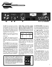
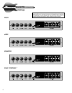
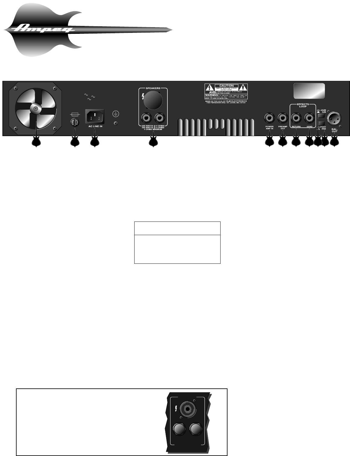
The Rear Panel
115VAC, 60Hz: T10A SLO BLO
100/115VAC, 50/60Hz: T8A SLO BLO
230VAC, 50/60Hz: T4A SLO BLO
MODEL:
SERIAL:
LINE: V ~ Hz
WATTS: MAX
SVT-GS
SVTGS126902U
120 60
16 17 18 19
20 21 22 25 262423
16. FAN: This temperature controlled,
variable speed fan draws cool air into
the amplifier, forcing heat out through
the exhaust vents (also on the rear
panel, between the speaker jacks and
the power amp in jack). Never block the
vent holes or the fan openings.
NOTE: It is not uncommon for the fan to
remain off when the amplifier is first
powered up.
17. FUSE: This protects the unit from
damage due to overload conditions or
power line surges. If the fuse blows,
replace it only with the same size and
type.
18. AC LINE IN: Firmly plug the sup-
plied AC power cord into this socket,
pushing it in until it is fully seated. Plug
the male end of the cord into a ground-
ed AC outlet. DO NOT DEFEAT THE
GROUND PRONG OF THE AC PLUG!
19. SPEAKER OUTPUTS: Use these
jacks to connect the amplifier to your
speaker(s) using cables terminated with
1/4” plugs. Always use high-quality
speaker cables for these connections.
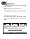
NOTE: When connecting multiple
speaker cabinets to the amplifier,
keep the overall impedance at or
above four ohms! The following chart
shows the total impedance load when
connecting speaker cabinets in parallel:
20. POWER AMP IN: This mono jack
allows you to feed the preamp output of
another amplifier to the input of the
internal power amp. This disconnects
the SVT’s preamp.
21. PREAMP OUT: A post-EQ signal
may be taken from this jack to be sent
to the house mixing board, recording
console or external power amplifier.
22. EFFECTS RETURN: To use an
external effects device, connect the
OUTPUT of the device to the Return
jack using a shielded cable. This feeds
the processed signal into the amp’s
Master section.
23. EFFECTS SEND: Connect the out-
put from the Send jack to the INPUT of
your effects using shielded cable. This
sends a post-EQ signal to your effects.
24. -20dB SWITCH : This control
adjusts the output level at the Balanced
Line Output jack (#26). The control
works independently from the front
panel Master control. Pushing the
switch in activates the -20dB pad,
allowing use of microphone inputs on a
mixer without overdriving the inputs.
25. PRE/POST SWITCH: You can
select either Pre or Post EQ for the sig-
nal at the Balanced Out jack (#26) with
this switch. With the switch in the OUT
position, the signal at the jacks will be
Pre-EQ. This is a direct output not
affected by any EQ or boost settings.
With the switch in, the signal is Post-EQ
and is controlled and modified by the
tone controls, Graphic EQ, and Effects
Loop.
26. BALANCED OUTPUT: This XLR-
type connector supplies a balanced
preamp output signal for connecting to
a house mixing board, recording con-
sole or external amplifiers with bal-
anced inputs. The signal can be set to
Pre or Post EQ by the back panel
Pre/Post switch (#25). The level can be
adjusted for either mic or line type
inputs using the -20dB switch (#24).
Cabinet # of Total
Impedance Cabs Impedance
8Ω 24Ω
16Ω 28Ω
16Ω 44Ω
SPEAKERS
200W @ 8 OHMS
350W @ 4 OHMS
4 OHMS MINIMUM
IMPORTANT NOTE ABOUT CERTAIN EXPORT
UNITS: In some areas 1/4” speaker jacks are not
acceptable for use on amplifiers capable of high out-
put power levels. For this reason the Speaker jacks
on your amplifier may resemble the illustration to the
right. Connect the amplifier to your speaker(s) using
cables rated for very high output power, terminated
with the appropriate connectors.