


4
SVT-2 PRO Bass Amplifier
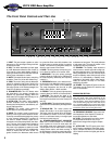
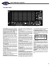
The Front Panel Controls and Their Use
1. INPUT: This jack accepts a passive or active
instrument or a line level signal through a shield-
ed instrument cable.
2. PAD: This switch attenuates the input signal
by 15dB. Attenuation allows the Gain control (4)
to be used in a more usable (higher) position. If
clipping is indicated even with the Gain control all
the way down, attenuation is needed.
3. MUTE:This switch kills the input to everything
except the Tuner Out (34) to allow silent tuning.
4. GAIN: This control, along with the Attenuator
switch (2), adjusts the basic level of signal in the
preamp. To get the best signal to noise ratio, set
this control so that, on the loudest passages, the
Peak LED (5) flashes occasionally.
5. PEAK/MUTE LED: This LED flashes when
the signal level in the preamp (excluding the
Graphic EQ) approaches clipping. When the
Mute switch (3) is engaged, this LED stays on as
a visual indicator that Mute is active.
6. ULTRA LOW: This switch, when engaged,
provides emphasis to the low frequencies by
boosting the low frequencies and selectively cut-
ting the mid frequencies.
7. BRIGHT: This switch, when pushed IN,
boosts upper mid and high frequencies.
8. DRIVE: This control is used to overdrive the
preamp in order to get various distortion sounds.
In the fully counterclockwise position the preamp
is in the cleanest, traditional SVT condition. As
the control is rotated clockwise, signal level is
increased to drive the preamp harder (into distor-
tion). The tone of the signal is also changed to
provide a smoother overdrive. The tone controls
may have to be readjusted to obtain the overall
desired tone. The Gain control (4) and Attenuator
switch (2) interact with the Drive control. For
greater overdrive, the Attenuator switch should
be out and the Drive control fully clockwise. Use
the Gain control to set the amount of overdrive
desired. The Peak LED (5) will glow a steady red
when the amp is used in this manner.
9. BASS: This is the primary low frequency con-
trol. It allows for 12dB of cut or boost at 40Hz.
10. MIDRANGE: This is the primary midrange
control. It allows for 15dB of cut or 12dB boost at
the center frequency selected by the Frequency
control (11).
11. FREQUENCY: Allows you to select the cen-
ter frequency for the Midrange control (10), giving
you a choice of five “voices” for the Midrange.
The center frequencies are (from left to right)
220Hz, 450Hz, 800Hz, 1.6kHz and 3kHz.
12. TREBLE: This is the primary high frequency
control. It allows for 12dB of cut or boost at 4kHz.
13. MASTER: This controls the signal to the
power amp and therefore the overall listening
level. It also controls the level to the Preamp Out
jack (27).
14. ULTRA HIGH: This switch boosts higher fre-
quencies than those affected by the Bright switch
(7).
15. GRAPHIC EQ: This switch places the
Graphic EQ circuitry in or out of the signal path.
The switch must be pushed IN for the Graphic
EQ footswitch to function. In the OUT position,
there is no solid state circuitry in the signal path
from input to power amp out.
16. STANDBY/POWER/FAULT INDICATOR
LED: This is a multi functional LED. In Standby
mode, it glows red. In the On mode (when the
high voltage comes on) it glows green. If it does
not turn green in the On mode, there is no high
voltage present and the unit needs servicing. If
the amp detects a fault in the power tube circuit,
the high voltage is turned off and the LED flash-
es between red and green. This usually indicates
a bad power tube. The amp will remain in this
condition until the unit is turned off.
17. STANDBY: The Standby mode allows the
tubes to warm or remain warm without high volt-
age being applied to them. This extends tube life.
During short periods of non-use, the amp should
be put into Standby mode. When the amp is first
turned on, it is automatically in Standby mode,
regardless of the switch position. After approxi-
mately 20 seconds, the amp is in the mode
selected by the switch.
18. POWER: This supplies AC power to the unit.
This switch must be turned off to reset the amp
after a Fault condition.
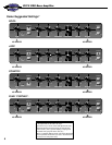
GRAPHIC EQ SECTION
The Graphic EQ can be used in two ways: 1) To fine
tune your sound, make small adjustments at the
desired frequencies and leave the EQ on throughout
the entire session. (This is great for adapting to varying
room acoustics when going from club to club, etc.) 2)
For a completely different sound, make larger adjust-
ments and only activate the EQ when you want a “sec-
ond channel” sound (such as during bass solos).
19. FREQUENCY SLIDERS: These control the
nine frequencies of the Graphic EQ section at
the points indicated over each slider.
20. LEVEL: This adjusts the level of the signal
to compensate for boosts or cuts, or for a
desired level change when using the Graphic
EQ.
21. ACTIVE LED: This LED glows green when
the EQ section is enabled by the proper combi-
nation of Graphic EQ switch (15) and footswitch
(35). It flashes red when the signal gets close to
clipping.
-15dB PAD
MUTE
PEAK /
MUTE
ULTRA LO
BRIGHT
ULTRA HI
GRAPHIC EQ
MASTERTREBLEFREQUENCYMIDRANGEBASSDRIVEGAININPUT POWERSTANDBY
-12dB
0
+12dB
-10dB
0
+8dB
40Hz 90Hz 180Hz300Hz500Hz 1kHz 2kHz 4kHz 10kHz LEVEL
ACTIVE / PEAK
1 4 8 9 10 11 12 13 17 181652 3 6 7 14 15
19 20 21