


5
SVT-2 PRO Bass Amplifier
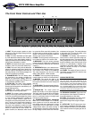
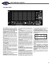
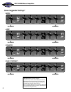
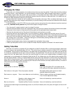
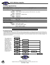
The Rear Panel
22. AC LINE IN: Firmly plug the supplied AC
power cord into this socket, pushing it in until it is
fully seated. Plug the male end of the cord into a
grounded AC outlet. DO NOT DEFEAT THE
GROUND PRONG OF THE AC PLUG!
23. FUSE: The fuse protects the amplifier from
damage due to line current faults and other con-
ditions. If the fuse blows, replace it only with the
same size and type as listed on the amplifier.
24. POLARITY: Place this switch in the position
that provides the least electrical buzz from the
unit.
25. BIAS SECTION: These controls and LEDs
allow the user to properly bias the power amp.
26. SLAVE OUT: This jack receives the same
signal that is being sent to the power amp. It is
useful for powering another amp (slave) from
this unit’s preamp.
27. PREAMP OUT: This jack carries the post-
Master (13) signal. It does not break the path to
the power amp. This signal can be used to feed
an external power amplifier, mixing console, or
house PA system.
28. POWER AMP IN: This jack accepts a signal
to be sent to the power amp and the Slave Out
jack (26). It does break the path from the
Preamp Out jack (27). This can be used as a
post-Master (13) patch point.
29. LEVEL: This control adjusts the level of the
signal at the Balanced Out jack (31).
30. PRE/POST: This switch selects a direct out
from the bass (Pre) in the OUT position and the
preamp signal just before the Master (Post) in
the IN position to be sent to the Balanced Out
jack (31).
31. BALANCED OUT: This XLR-type jack is the
output as selected by the Pre/Post switch and
adjusted by the Level control (29). This signal
can be used to feed an external power amplifier,
mixing console, or house PA system.
32. EFFECTS LOOP SEND: This is a post-EQ,
pre-Master (13) patch point send jack. It does
not break the path through the preamp. When
using an external signal processor, connect the
INPUT of the effect to this jack using a shielded
instrument cable to send the signal to the effect
for processing.
33. EFFECTS LOOP RETURN: This is a pre-
Master (13) patch point return jack. It breaks the
path through the preamp. When using an exter-
nal signal processor, connect the OUTPUT of
the effect to this jack using a shielded instrument
cable to feed the processed signal into the
power amp section.
34. TUNER OUT: This is a direct output from the
instrument which can be routed to a tuner. It is
the only output that stays active when the Mute
switch (3) is engaged.
35. FOOTSWITCH: This is a stereo jack which
will operate with a standard dual footswitch. The
tip of the plug controls the Mute operation, the
ring controls the Graphic EQ operation, while the
sleeve acts as a ground common to both. With
the footswitch inserted, both the front panel and
the footswitch Mute switches are active. The
front panel Graphic EQ switch (15) must be IN
for the Graphic EQ footswitch to operate.
36. IMPEDANCE SELECTOR: Use this switch
to match the output impedance of the amp to the
speaker(s) being used (2 or 4 ohms). For help in
deciding the impedance of your system, consult
the chart below.
37. SPEAKERS: These jacks are provided for
connecting speakers to the unit. While the 1/4”
jacks are convenient, the Speakon
®
connector is
preferred for carrying the heavy current from this
amplifier.
NOTE: In some areas the 1/4” speaker jacks
are not acceptable for use on amplifiers
capable of high output power levels. For this
reason your amplifier may have been
shipped with the 1/4” jacks sealed – use only
the Speakon
®
jack for connecting your
speakers.
38. This is a 1/4-20 weld-nut which can be used
to provide additional support for the rear of the
unit.
Cabinet # of Total
Impedance Cabs Impedance
4Ω 22Ω
8Ω 24Ω
8Ω 42Ω
CAUTION:
TO REDUCE THE RISK OF FIRE, REPLACE
FUSE WITH SAME TYPE AND RATING.
ATTENTION:
UTILISER UN FUSIBLE DE RECHANGE
DE MEME TYPE.
AC LINE IN
POLARITY
TO ADJUST BIAS: ALLOW UNIT TO WARM UP
FOR 20 MINUTES. ADJUST BIAS CONTROLS
SO THAT ONLY GREEN LED'S ARE LIT. SEE
MANUAL IF THIS CONDITION CAN NOT BE MET.
BIAS 1
CONTROL
–
+
SLAVE
OUT
BALANCED OUT
BALANCED LINE OUT EFFECTS
LOOP
LEVEL
PRE
PREAMP OUT
POWER AMP IN
MODEL
SERIAL #
SVT2PRO
MADE IN THE U.S.A. BY - SLM ELECTRONICS
1400 FERGUSON AVENUE - ST. LOUIS, MO 63133
100/115VAC - 10A SLO BLO, 125V
230VAC - 5A SLO BLO, 250V
BIAS 2
CONTROL
TUNER OUT
FOOTSWITCH
SEND
RETURN
POST
IMPEDANCE
SELECTOR
SPEAKERS
300 WATTS @
SELECTED
IMPEDANCE
WARNING:
HIGH DECIBEL
OUTPUT –
SEE OWNER'S
MANUAL
4 OHM
2 OHM
CAUTION
RISK OF ELECTRIC
SHOCK
AVIS:
TO REDUCE THE RISK OF FIRE
OR ELECTRIC SHOCK, DO NOT
EXPOSE THIS EQUIP-MENT TO
RAIN OR MOISTURE.
RISQUE DE CHOC
ELEC-TRIQUE –
NE PAS
OUVRIR
22 2524 38 26 28 29 30 3127 3332 35
36
37
3423