


4
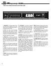
The Front Panel Controls and Their Use
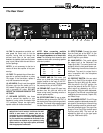
SVT-350H
Gain Graphic EqualizerBass Ultra Mid Treble Master Power
Limit
Limit
EQ On
EQ On
On
On
Pad
Pad
Peak
Peak
40Hz
40Hz
80Hz
80Hz
150Hz
150Hz
300Hz
300Hz
600Hz
600Hz
900Hz
900Hz
2kHz
2kHz
5kHz
5kHz
9kHz
9kHz
0
–12dB
12dB
+12dB
+12dB
0dB
0dB
010
5
4
3
2
1
9
8
7
6
010
5
4
3
2
1
9
8
7
6
010
5
4
3
2
1
9
8
7
6
010
5
4
3
2
1
9
8
7
6
010
5
4
3
2
1
9
8
7
6
2 3 4 5 6 7 8 9 10 11 12 131
1. 0dB (INPUT): The signal output from an
instrument (active or passive) or a line level
signal may be connected here by means of
a shielded instrument cable.
2. PAD: This switch, when depressed,
attenuates the input signal by 15dB.
Attenuation allows the Gain control (#4) to
be used in a more usable (higher) position.
If clipping is indicated with the Gain control
way down, attenuation is needed.
3. PEAK LED: This LED flashes when the
signal level into the preamp (excluding the
graphic EQ) approaches clipping. Adjust
the Gain control (#4) until a strong signal
from your instrument causes this LED to
flicker.
NOTE: If the LED flashes frequently with
the gain at a low setting, use the Pad (#2)
to attenuate the input signal and readjust
the Gain.
4. GAIN: This serves as the input level
control for the amplifier. For the best signal-
to-noise set this control so the Peak LED
(#3) flashes when you strike a string fairly
hard.
5. BASS: This is the primary low frequency
control. It allows for a range of 8dB of cut
or boost at 50Hz.
6. ULTRA-MID: The primary midrange
control. Rotate the control to the left of cen-
ter for a “contoured” sound (more distant,
less midrange output) or to the right of cen-
ter for a sound which really cuts through.
7. TREBLE: This is the primary high fre-
quency control. It allows for a range of
12dB boost or 19dB of cut at 5kHz.
8. MASTER: Set the overall output level of
the amplifier with this control. The Effects
Loop and Balanced Out (#20-24) are not
affected by the Master control.
9. LIMIT: The SVT-350H uses an internal
Optocoupler Limiter to assist in keeping the
power amplifier’s output “clean” at extreme
volume levels. (All amplifiers may begin to
clip their output signals as they approach
maximum output levels, resulting in poten-
tially damaging distortion.) To engage the
Limiter, depress the Limit switch. The adja-
cent LED will illuminate whenever the lim-
iter circuit is activated. This indicates that
the amplifier is nearing full output and the
limiter is keeping peak signals from clipping
the output.
NOTE: Playing at full power with the Limiter
off will give you increased output power, but
the sound may be distorted. Use discretion
when playing without the Limiter.
10. EQ ON SWITCH: Depress this switch
to activate the Graphic EQ. The adjacent
LED will illuminate when the EQ is on.
11. GRAPHIC EQ: These sliders control
the output of the frequencies indicated
below each control. The center position of
each control is flat (no boost or cut).
12. POWER ON LED: This LED indicator
illuminates when the POWER switch (#15)
is ON.
13. POWER SWITCH: This heavy-duty
rocker switch applies the power to the
amplifier. The amp is ON when the top of
the switch is depressed, OFF when the
bottom of the switch is depressed.