


4
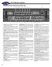
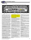
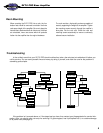
The Front Panel Controls and Their Use
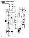
SVT-5 PRO Bass Amplifier
1 4 8 10 13 22 28 292395 24 272 3 6 7 11 12 25 26
14 17 18 19 20 21 3015 16
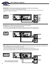
1. INPUT: Connect your bass guitar here by means
of a shielded instrument cable.
2. -15dB: This switch, when depressed, will atten-
uate the input signal by 15dB. If your bass has
active pickups, depress this switch to better
accommodate its output signal level.
3. MUTE: This switch, when depressed, mutes all
outputs except the Tuner Out (#54). This allows you
to tune your bass with an electronic tuner without
having to adjust any levels or turn down your house
volume.
NOTE: A footswitch can also be used mute the out-
puts if this switch is in the “out” position. This switch
remains active when a footswitch is connected.
(See #43, rear panel.)
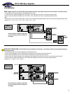
CLEAN CHANNEL:
4. GAIN: This control adjusts the level of the signal
going to the clean preamp. Adjust this control until
the Peak LED (#5) flashes on strong signal peaks
(but is not continuously illuminated while playing).
To obtain the best signal to noise ratio, set the Gain
control to the highest possible setting and adjust the
clean channel Volume (#13) and Master control
(#23) to obtain the desired volume level.
5. PEAK LED: This LED will illuminate when the
preamp signal approaches its clipping level, indi-
cating optimum gain setting.
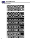
6. ULTRA HI: This switch, when depressed,
increases the high frequency output by 7dB at
15kHz.
7. ULTRA LO: This switch, when depressed,
increases the low frequency output by 5dB at 30Hz.
8. BASS: This control provides an adjustment
range of 20dB at 40Hz.
9. MID: This control provides an adjustment range
21dB at 300Hz.
10. TREBLE: This control provides an adjustment
range of 18dB at 10kHz.
11. COMPRESSION: This switch, when depressed,
activates the compression circuit which evens out
your volume by governing the gain of the preamp.
The amount of compression is determined by the
setting of the Gain control (#4).
12. COMBINE: This switch, when depressed,
allows the clean channel to remain active when the
overdrive channel is selected, combining the two
channels to create a different-sounding “third chan-
nel.” A footswitch connected to the Ch/Combine
jack (#42) overrides this switch.
NOTE: The Channel Select switch (#25) must be
depressed for the Combine function to operate.
13. VOLUME: This control adjusts the output level
for the clean channel.
OVERDRIVE CHANNEL:
14. GAIN: This control adjusts the level of the sig-
nal going to the overdrive preamp. As this control is
increased, so is the amount of overdrive distortion
added to your sound.
15. BOOST: This switch, when depressed, adds
gain and tone shaping to the overdrive channel sig-
nal for heavy distortion.
16. GATE: This switch, when depressed, activates
a noise gate which keeps the overdrive channel
silent when no input signal is present.
17. BASS: This control provides an adjustment of
12dB of cut or boost at 100Hz.
18. MID: This control provides an adjustment of
5dB of cut or 20dB of boost at 300Hz - 2kHz,
depending on the setting of the Frequency control
(#19).
19. FREQUENCY: This control adjusts the center
frequency of the Mid control (#18), from 300Hz at
the fully counterclockwise position to 1.5kHz at the
fully clockwise position.
20. TREBLE: This control provides an adjustment
of 12dB of cut or boost at 7kHz.
21. VOLUME: This control adjusts the output level
for the overdrive channel.
22. OCTAVE: This control adjusts the output level
for an added signal which is one octave lower than
the instrument’s original signal. This signal is
dependent on the clean channel’s Gain control (#4)
and can be switched on and off by means of a
footswitch connected to the Octave/Mute jack
(#43). The effectiveness of this signal depends on
playing style, pickup selection and neck position.
23. MASTER: This control adjusts the overall out-
put level of the amplifier.
24. LIMIT: This LED illuminates when the internal
limit circuit is activated. This indicates that the
amplifier is nearing full output and the limiter is
keeping it from clipping the output signal.
25. CHANNEL SELECT: This switch selects the
clean channel in the out position and the overdrive
channel when depressed. A footswitch connected
to the Ch/Combine jack (#42) overrides this switch.
26. LIMIT DEFEAT: This switch, when depressed,
deactivates the internal limit circuit. This may allow
an increase in output power, but the signal may be
distorted. A distorted signal at high output levels
could damage the components of your speaker
system. Use discretion when playing with the limiter
deactivated to avoid damaging your speakers.
27. OD/CLEAN LEDS: These LEDs indicate which
channel is selected.
28. CROSSOVER FREQUENCY: This control
determines the crossover frequency between the
Biamp High and Biamp Low Output jacks (#44).
29. CROSSOVER BALANCE: This control adjusts
the relative levels between the Biamp High and
Biamp Low Output jacks (#44).
30. POWER: This switch applies power to the
amplifier: the amp is ON when the top of the switch
is depressed, OFF when the bottom of the switch is
depressed.