


5
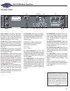
The Rear Panel
SVT-8 PRO Bass Amplifier
20. AC LINE IN: Firmly insert the supplied AC
power cord into this socket until it is fully seat-
ed. Plug the male end of the cord into a
grounded AC outlet. DO NOT DEFEATTHE
GROUND PRONG OFTHE AC PLUG!
21. BAL. OUT: This jack supplies a line level
signal for connection to a house mixing board,
recording console or external amplifier. The sig-
nal level at this jack is governed by the Post/Pre
switch (#23).
22. GND/LIFT:Use this switch to lift the ground
connection at the Bal. Out jack to help eliminate
hum in the Bal. Out signal.
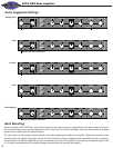
23. POST/PRE:The signal at the Bal. Out jack
(#21) can be set to either Pre or Post-EQ with
this switch. With the swi
tch in the OUTposition,
the signal at the jacks is Pre-EQ. This is a direct
output not affected by any EQ or boost settings.
With the switch depressed, the signal is Post-
EQ and is controlled and modified by the tone
controls and the effects loop.
24: TUNER OUT: This jack is provided for con-
nection to an electronic tuner and is always
“live,” even when the Mute switch (#3) is
engaged. This allows for “silent tuning” as well
as a monitor feed which stays hot even when
the house mix is muted.
25. SPEAKERS: These output jacks supply
speaker-level power to the speaker cabinet.
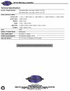
The rated power output is 1300 watts rms
into 4 ohms or 2500 watts rms into 2 ohms
(minimum load).
WARNING: Use speaker cables to make
the connections. Do not use instrument
cables as they may overheat.
Pin 1+ = hot
Pin 1– = return
26. CIRCUITBREAKER: The SVT-8 PRO
employs an AC line circuit breaker to
help pro-
tect against damages due to excessive current
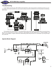
demands. If the amplifier stops working, check
the circuit breaker.
27: POWER AMPIN: This jack connects an
external preamp directly to the power amp.
When using an external source, connect the
output of the source to this jack by means of a
shielded signal cable to feed the signal into the
power amp section. The internal signal is dis-
connected when a connector is inserted into
this jack.
28. PREAMP OUT:Use this jack to send a sig-
nal from the internal preamp to an auxiliary
power amplifier, mixing console, monitor sys-
tem, or
house PAsystem. The signal at this
jack is post-EQ.
29. EFFECTSLOOPRETURN: When using
an external signal processor, connect the out-
put of the device to this jack by means of a
shielded signal cable.
30. EFFECTSLOOPSEND: When using an
external signal processor, connect this jack to
the input of the device by means of a shielded
signal cable.
31. FOOTSWITCH: Connect a two-button
(ring/tip/sleeve) footswitch to this jack to control
the Power Reduction and the Mute functions.
(Mute = tip/sleeve; Power Reduction = ring/
sleeve.)
NOTE: A footswitch may be purchased at
your local Ampeg Dealer or ordered directly from
LOUD Technologies Inc. Be sure to ask for
model #AFP2.
IMPORTANT: This unit employs forced air
cooling by means of an internal fan. The
rear and side ventillation slots must remain
unobstructed when operating this amplifier.
When mounting the unit in a rack make sure
there is ample room for proper air circulation.
The rack must be constructed and positioned
in such a manner to allow proper air flow and
the exhausting of hot air away from the rack
at all times.
WA RNING:
Made In The U.S.A .
L OUD T E CH NOL OGIE S , I NC .
100Ð240V 50/60Hz 300VA
250 0W @ 2 OH MS
130 0W @ 4 OH MS
C LA SS 2 WIR ING
T his devic e com plies with part 15 of the FCC R ul es .
Op erati on is s ub jec t to the followi ng two c ond ition s:
this device m ay not caus e har mfu l in terferenc e, and th is
dev ice mus t acc ept any interfere nce r ece ive d, includ ing
inte rfer enc e that may caus e u ndes ir ed oper ation .
26 27 28 3129 30
20 2421 2522 23
26 27 28 3129 30
20 2421 2522 23
W