


5
Operating Manual - DLM-821 Stereo Ducking Line/Microphone Mixer
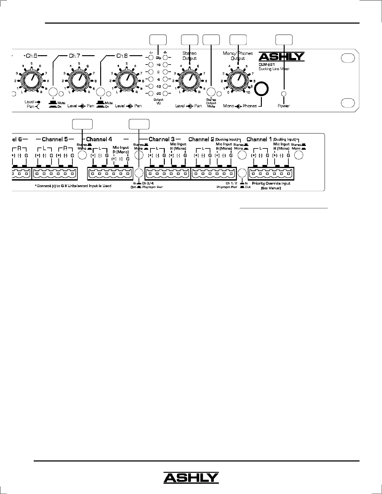
5.9 Power Switch
The DLM-821 power s witch is on the back panel.
When it is pressed in the front panel power LED will be-
come lit.
5.10 Mono Output Mic/Line Switch
This switch selects between a 0dBu (out posi-
tion) line level or -40dBu (in position) mic level signal
feeding the Mono output connector.
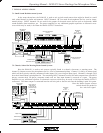
5.11 Stereo/Mono Input Switches
These four pushbutton switches allow selection
between a stereo or mono signal connection to input chan-
nels 1 through 4 respectively. In the Out position, stereo
left and right cables should be connected. In the in posi-
tion, a mono cable should be connected to the R(Mono)
connector which then internally feeds the signal to both
left and right sides.
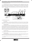
5.12 Phantom Power Switches
There is a phantom power switch for channels 1
and 2 and a phantom power switch for channels 3 and 4.
Pushing the switch in applies +18VDC to the (+) and (-)
input terminals of the two associated channels to power
condenser mics. The input channels should be muted
using the On/Mute switches when switching phantom
power on or off to avoid any pop noises.
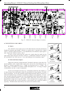
Internal PCB Jumper Options:
5.13 Ch. 2 Detect Enable *
Internal jumper J1 allows enabling or disabling
the ducker detector for ch. 2. (factory default is enabled)
5.14 Ducking Level *
Internal jumper J16 allows selection between
-20dB ducking level and -90 dB ducking level. (factory
default is -20dB)
5.15 Ch. 1 Priority *
Internal jumper J6 allows enabling ch. 1 to have
priority over ch. 2 and fully attenuate channels 2-8. This
feature is useful for applying an emergency page or alarm
on channel 1 and applying a normal host page input on
ch. 2. (factory default is ch.1 priority disabled)
5.16 Left and Right Ducking Enable *
Internal jumpers J14 and J15 allow the left and
right signal ducking to be enabled or disabled indepen-
dently. (factory default is left and right ducking enabled)
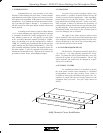
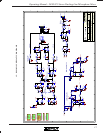
* For internal jumper adjustments, remove AC
cord from rear of unit and refer to a qualified service
technician. (see PCB jumper locations in fig. 5.2)