


Page - 6 Operator Manual – MX-406 Mixer
Copyright© 2007 – Ashly Audio Inc.
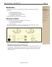
Physical Description
The MX-406 is 2RU, and weighs 13 pounds.
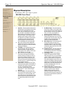
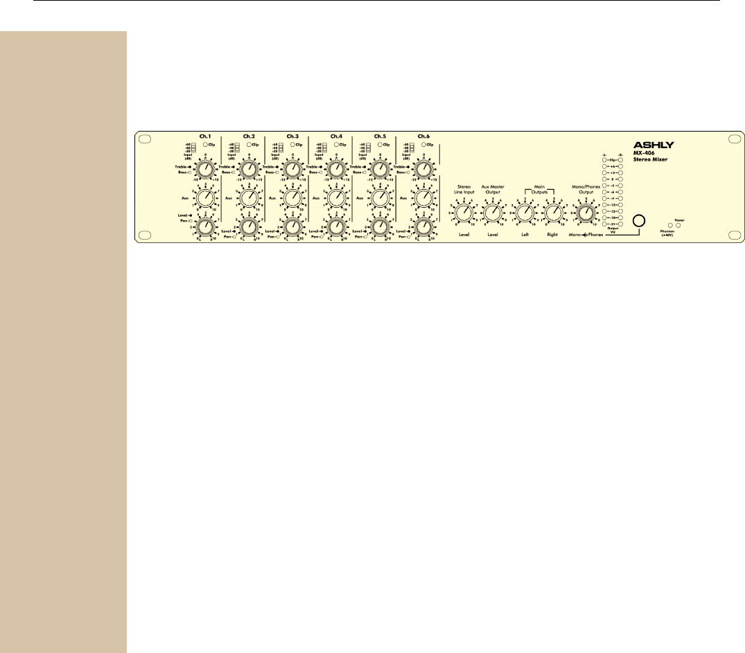
MX-406 Front Panel
1. Input Gain - This three position switch sets the
operating level of the microphone and line input
preamp. The corresponding switch values -
20db, -40dB, and -60dB refer not to the actual
gain, but rather to the expected nominal input
signal strength. Line level inputs (1/4" jack) will
likely use a setting of -20dB, while mic inputs
generally require a setting of -40dB for close
mic applications, and -60dB for quieter signals.
If a channel's clip LED is blinking, first turn
down that channel's level control. If the clip
LED is still flashing, turn down the input gain.
2. Clip - Input Clip LEDs monitor critical points
within the input channel. The clip LED turns on
whenever any portion of the audio path reaches
dB below actual clipping.
3. Treble/Bass - This concentric knob is used for
broad EQ changes to each input channel.
Channel EQ consists of a high shelf control
(treble) at 4KHz, and a 250Hz low shelf control
(bass). EQ boost or cut is ±12dB.
4. Aux - The aux send is an additional level
control used to send signal from each input
channel to monitors or an effect unit. The aux
master output combines all channel aux level
signals. The aux control is factory set to pre-
fader, pre-EQ, but can be internally switched to
post-fader, post EQ. To make this change, refer
to the procedure on page 8.
5. Level and Pan - This concentric knob adjusts
the level and stereo position of each channel. If
a channel's level control is always turned up to
9 or more, try increasing the gain first.
Conversely, if the level control is consistently
turned down to 1 or less, decrease the gain
setting first.
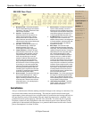
6. Stereo Line Input - This control adjusts the
level of the RCA jack stereo line input. It can be
used for tape, CD, or DVD audio inputs, and
can also be used for a stereo effect return. The
stereo line input can be used as stacking inputs
for supplementing the MX-406 with another
mixer.
7. Aux Master Output - This control adjust the
level of the aux master 1/4" jack output, which
gets its signal from the six aux level controls on
the input channels. It is used for an effects unit
send, or can drive a power amplifier for
monitors or an extra loudspeaker zone.
8. Stereo Output Level - These two controls
determine the signal level to the 1/4" jack left
and right outputs. They are used to drive power
amplifiers for the main loudspeakers, or to
connect to a stereo recording device.
9. Mono Output Level - This control adjusts the
level of the summed mono output. It is
completely independent of the main left and
right master controls. In other words, changes
to either left or right output level will not affect
the mono output level.
10. Headphones Level - This control adjusts the
level of the stereo signal to the headphone
jack. Headphones should have an impedance
of 600 ohms or greater.
11. Output Meters - A pair of peak reading 10
segment LED meters are used to indicate
stereo output level in VU. 0 VU is equivalent to
+4 dBu (1.228Vrms). Green LED's are used
below 0 VU, yellow above 0 VU and two red
LED's indicate clipping. The clip LED's turn on
3dB below actual clipping, detecting excessive
signal level on any critical audio path within the
master section. If all outputs are turned down
and there is still clipping, then one or more
inputs must be turned down.
12. Phantom Power LED - The phantom power
switch is on the back panel. When the switch is
pressed in, the LED is lit and +48VDC is
applied to all six mic inputs for use with
condenser microphones. If there is a mix of
both condenser and dynamic microphones, the
phantom power will not affect the operation of
most dynamic mics.
Safety Instructions – 3
Introduction - 4
MX-406 Mixer – 5
Connectors & Cables – 5
Physical Description - 6
Front Panel
Rear Panel
Installation – 7
Typical Applications - 8
Factory Configs - 8
Troubleshooting - 9
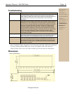
Dimensions - 9
Specifications - 10
Warranty - 11