


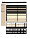

Page - 6 Operator Manual – MX-508 Mixer
Copyright© 2006 – Ashly Audio Inc.
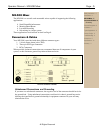
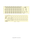
Physical Description
The MX-508 is 4RU, and weighs 19 pounds.
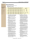
MX-508 Front Panel
1. Input Level (Gain) - Sets the operating level of
the Mic preamp and Line Input. It is desirable to
set the Gain control as high as possible while
still leaving enough headroom to prevent
distortion.
2. Mic-Line Switch - Switches between the XLR
microphone input or the 1/4" line input jack as
the signal source. It can also serve as a
"channel mute" when switched to an unused
input.
3. Channel Clip Indicator - This peak indicator
monitors all level critical points in the input
channel and illuminates if any of them reach
levels within 3 dB of clipping.
4. Equalization - EQ consists of a high shelf
control at 15KHz (middle of shelf), a sweepable
mid control, and a 70Hz low shelf control. The
mid control is sweepable from 140Hz to 8KHz
with a bandwidth of approximately 1 octave.
5. Aux Sends - This pair of level controls adjust
the feed to monitors or effects units. Aux 1 is
factory preset to pre-fader, pre-EQ, while Aux 2
is post-fader, post-EQ. Both Aux sends can be
internally switched to pre or post fader/EQ.
6. Level and Pan - This concentric pair of
controls adjusts the level and stereo position of
the channel in the mix.
7. Aux Master Sends - These controls adjust the
overall gain of the output stages for the Aux 1
and Aux 2 outputs.
8. Aux Master Returns With Pan - These
controls adjust the returning signal from effects
units or auxiliary inputs to the Left and Right
outputs. Return 1 is stereo and return 2 is
mono. If only the right connection to return 1 is
used, this return will function as mono with pan.
9. Tape/CD Input and Send - Adjusts the
Tape/CD input to the Main Stereo outputs. The
outer concentric control labeled "To Aux 1"
sums the stereo Tape/CD signal to mono and
applies it to the Aux 1 Master group (pre-fader)
for use with monitors or effects.
10. Output Meters - A pair of peak reading 10
segment LED meters are used to indicate
output level. Green < 0 VU, Yellow >0 VU, and
Red = clipping. This meter pair is switchable
between the Main Left and Right, or the Aux 1
and 2 outputs. The red clip LED's will illuminate
if the summing amplifiers are clipping even if
the main output controls are off. Note: The
output meters are accurately calibrated to the
transformerless output levels, but not
necessarily the transformer-balanced outputs.
11. Main Output Level - These controls determine
the level of both transformer balanced and
transformerless output stages for the Main Left
and Right outputs.
12. Main Output Mutes - Switches off both the
transformer-balanced outputs as well as the
1/4" stereo outputs, indicated by the red LED
near the switch. The headphone and metering
functions continue uninterrupted.
13. Phantom Power Switch - This front panel
switch enables the +48 Volt phantom power for
condenser microphones. One switch controls
all the inputs. If you have both condenser and
dynamic microphones, the phantom power will
not affect the operation of the dynamic mics.
14. Mono Output Level - This control adjusts the
level of the summed mono output. It is
completely independent of the Main Left and
Right masters.
15. Headphones Level - This control adjusts the
level of the designated output signal (Mains or
Aux) to the headphone jack.
16. Meter/Phones Select - This switch selects
either the Main Left/Right outputs or the Aux
1/Aux 2 outputs to the LED meters and the
headphone jack.
17. Headphone Output - This front panel 1/4" TRS
connector feeds a standard set of stereo
headphones. A selector switch that also
controls the level meter allows monitoring the
main or Aux outputs.
Safety Instructions – 3
Introduction - 4
MX-508 Mixer – 5
Connectors & Cables – 5
Physical Description - 6
Front Panel
Rear Panel
Installation – 7
Typical Applications - 8
Factory Configs - 8
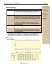
Troubleshooting - 9
Dimensions - 9
Specifications - 10
Warranty - 11