


Owner’s Manual
TSD-MIX31RL
3x1 Mic/Line Mixer
AtlasSound.com – 5 –
Specifications are subject to change without notice.
1601 Jack McKay Blvd. • Ennis, Texas 75119 U.S.A.
Telephone: 800.876.3333 • Fax: 800.765.3435
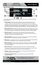
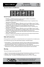
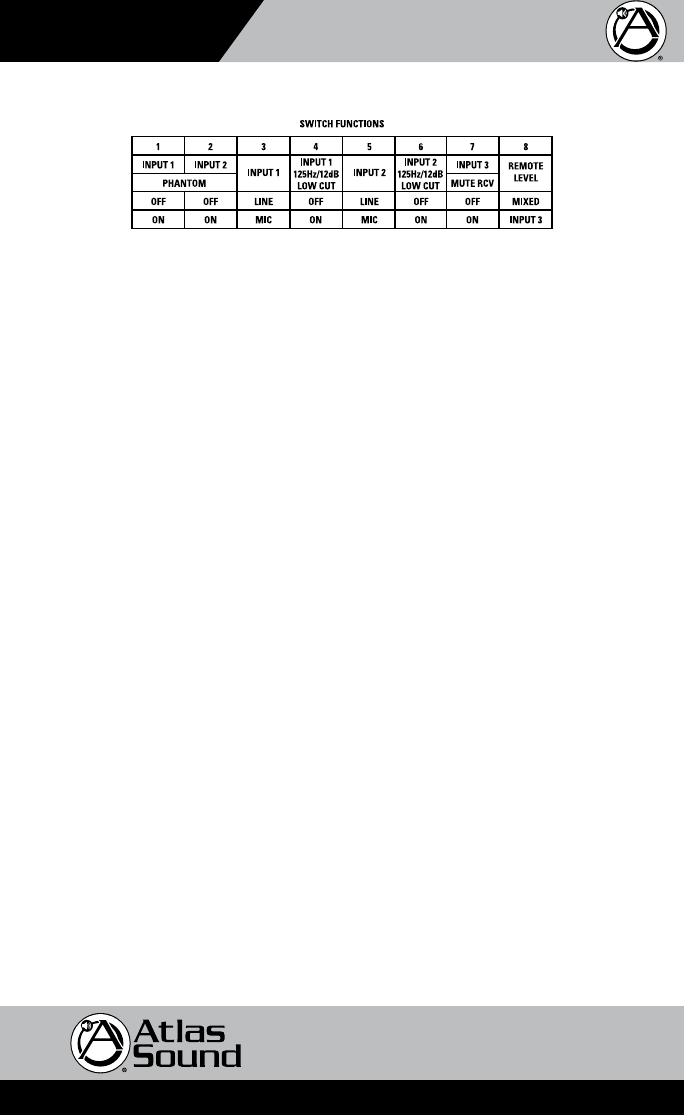
Dip Switch Function Identification
Switch Position
• DIPSW#1,2-24VDCPhantomPowerappliespowerforcondensermicoperationto
corresponding input terminal. Down position is On.
• DIPSW#3-InputMicorLineSelectforinputgainselectionforInput1.UppositionisLine,
down position is Microphone.
• DIPSW#4-LowCutFilterengagesat125Hzwitharolloffrateof12dBperoctave.Thislter
operates either in the Line or Mic mode and is available on Input 1. Ideal for vocal microphones
to reduce low frequency energy and to increase intelligibility. Down position is On.
• DIPSW#5-InputMicorLineSelectforinputgainselectionforInput2.UppositionisLine,
down position is Microphone.
• DIPSW#6-LowCutFilterengagesat125Hzwitharolloffrateof12dBperoctave.Thislter
operates either in the Line or Mic mode and is available on Input 2. Ideal for vocal microphones
to reduce low frequency energy and to increase intelligibility. Down position is On.
• DIPSW#7-Input3MuteReceivewillmuteaudiopresentatInput3whenaudioispresentat
Input 1. Down position is On.
• DIPSW#8-RemoteLevelsetswhethertheremotevolumecontroladjustsallinputsmixedor
Input 3 only. Up position is all inputs, down position is Input 3 only.
Knob and Security Cover
All front panel level controls feature a removable knob that can be replaced with an included security
cover.Followthesestepstopreventpotentiometerdamageorunwantedchanges.
1. Knob Installation - Turn the potentiometer shaft fully counter-clockwise. Align the knob indicator
to the lowest setting on the panel and the potentiometer shaft slot. Carefully press the knob onto
the potentiometer shaft. Do not force or damage may occur to the potentiometer.
2. Security Cover Installation – Remove the knob from the panel and insert the cover. Do not force or
damage may occur to the potentiometer. Small pliers may be required to remove the knobs.
Mounting
TherearethreewaystosecurelymountthisTSD:
1. Velcro™ - Each unit includes industrial grade Velcro™ with adhesive to adhere to any flat surface.
2. Brackets - Each unit includes two mounting brackets to secure to a cabinet or wall.
3. Rack Mount Panel - The optional TSD-RMK panel supports up to four TSDs in a 1RU space.