


DESCRIPTIONS AND FUNCTIONS
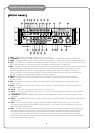
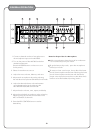
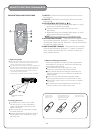
1. AC VOLTAGE SELECTOR - Check to make sure that the AC Voltage Selector switch is set to the proper
voltage for your area (120V/60Hz for the North America area) before plugging in the AC power cord
to the AC power outlet.
CAUTION: Unplug the
power cord from the power outlet before resetting the voltage
selector switch.
2. FUSE - Please turn off the AC power and unplug the AC power cord before replacing the fuse. (ONLY
replacing with the same type and rating of new fuse.When the AC VOLTAGE SELECTOR is
set to 115V,the
new fuse should have the rating of T6.3AL/250V..When theAC VOLTAGE SELECTOR is set to 230V,
the new fuse should have the rating of T4AL/250V.)
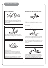
3. ~115V/60Hz ~230V/50Hz AC Power Input Terminal
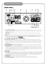
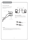
4. Speaker Output Terminals - Banana jacks are used as the speaker output terminals. The
overall
effective impedance of the speaker sets to each side (left or right side) of the speaker terminals needs to
be within the range of 4Ω To 16 . (Caution: If two sets of 8 speakers are connected to the same
speaker terminal, the effective
impedance of these two speakers will be 4, just one half of its original
impedance.)
5. KEY CONTROLLER - This KEY CONTROLLER 3.5mm input jack is to be connected to some special
equipment, such as a key control microphone.
6. VOLUME RESET - When this VO LUME RESET
is switched to the OFF position, both the MIC MASTER
VOLUME knob and the MUSIC MASTER VOLU ME knob will stay where they are after the main power is
turned on (after the power-on process). When this VOLU ME RESET is switched to the ON position, both
the MIC MASTER VOLUME knob and the MUSIC MASTER VO LUME knob will be turned to the minimum
position automatically after the main power is turned on.
7. Cooling Fa n
8. MIC INSERT - These are the TRS ¼” microphone effect inserts. The tip of the insert is used as the
audio
signal output (to the sound effect equipment), the ring of the insert is used as the audio signal input (from
the sound effect equipment), and the sleeve is used as the ground. The MIC1 is the microphone effect
insert for the MIC1 input.
The MIC2/3 is the microphone effect insert for the MIC2 and MIC3 inputs.
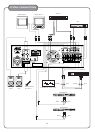
9. VIDEO INPUT - There are two video inputs, VCD and DVD.
10. VIDEO OUT - There are two independent video output jacks (each with its own driver).
11. MIC AU DI O OUTPUT - This audio output comprises the
microphone audio signal only.
AC AC AC
ΩΩ
Ω
T6.3AL/250V
T4AL/250V
6
1
2 3
4
5
6
7
8
9
10
11
12
13
14
15
16