


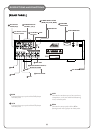
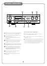
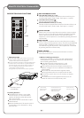

INPUT LEVEL
Turn this input level control to adjust the input
level. Turn the input level control counter-
clockwise to reduce the input level. Turn the input
level control clockwise to raise the input level.
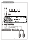
MUSIC EFFECT INPUT/OUTPUT JACKS
The EFFECT allows the AKJ7404 user to add any
sound effecter, such as an equalizer, as a part of
the music loop in the AKJ7404 unit. If a sound
effecter is not used, check to make sure that two
U-shaped connectors are connected from the IN
jacks to the OUT jacks. The first U-shaped
connector is to be connected from the white IN
jack to the white OUT jack. The second U-shaped
connector is to be connected from the red IN jack
to the red OUT jack. If a sound effecter is to be
placed in between the IN jacks and the OUT jacks,
the U-shaped connectors need to be removed from
the unit and make sure that these U-shaped
connectors are taped to the bottom of this unit for
future use. The IN jacks are to be connected to the
input ports of the sound effecter and the output
ports of the sound effecter are to be connected to
the OUT jacks.
PRE-OUT
The pre-amplifier audio output (PRE-OUT) can be
connected to an external power amplifier if needed.
FUSE
Please turn off the AC power and unplug the AC
cord before replacing the fuse (ONLY replacing
with the same type and rating of fuse).
VIDEO OUTPUT JACKS (1, 2, 3, 4)
These video output jacks are to be connected to
TV monitors.
MICROPHONE INPUT JACKS (MIC A AND MIC B)
These microphone input jacks are to be connected
to microphones. The MIC A jack is common to the
MIC 2 jack on the front panel. The MIC B jack is
common to the MIC 3 jack on the front panel.
MIC EFFECT INPUT/OUTPUT JACKS
The MIC EFFECT allows the AKJ7404 user to add
any sound effecter, such as an equalizer, as a part
of the microphone loop in the AKJ7404 unit. If a
sound effecter is not used, check to make sure that
the U-shaped connector is connected from the IN
jack to the OUT jack. If a sound effecter is to be
placed in between the IN jack and the OUT jack,
the U-shaped connector needs to be removed from
the unit and make sure that the U-shaped connector
is taped to the bottom of this unit for future use.
The IN jack is to be connected to the input port of the
sound effecter and the output port of the sound
effecter is to be connected to the OUT jack.
VOLTAGE SELECTOR
Check to make sure the AC Voltage Selector switch is
set to the proper voltage for your area (120V/60Hz
for the North America Area) before plugging in the
AC cord to the AC power outlet.
CAUTION: UNPLUG THE AC CORD FROM THE AC
POWER OUTLET BEFORE RESETTING THE AC
VOLTAGE SELECTOR SWITCH.
AC POWER CORD
Plug this cord into an AC wall outlet.
REMOTE IN
This jack is used to connect to an external remote
control sensor. When an external remote control
sensor is used, the remote sensor on the front
panel is deactivated.
AUTO ON OFF SWITCH
When this AUTO ON OFF switch is set to ON, the
audio/video input source will be automatically
switched to any audio/video input source with
signals. The priority of determining which audio/
video input source with signals to be selected is as
follows: video > audio and DVD>VCD>AUX>BGM.
When the AUTO ON OFF switch is set to OFF, the
audio/video input source needs to be selected
manually by pressing any of the input selection
buttons. The initial input source selection after
the power is turned on is the DVD input.
VIDEO INPUT JACKS (DVD, VCD, AUX, BGM)
These video input jacks are to be connected to a
DVD player, a VCD player, or other video units.
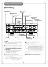
DESCRIPTIONS AND FUNCTIONS