


System Operation
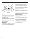
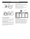
Setting Channels
Use the provided screwdriver to set the channel selector
switches on the receiver and transmitter to the same
frequency (Fig. A/C/D).
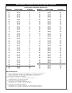
As an example using a non-”x” unit, setting the X10 selector
on “5” and the X1 selector on “2” designates channel 52,
operating at 734.625 MHz as shown on the chart on page 9.
(With an “x” unit, channel 52 is 662.625 MHz, as shown on
page 10.)
Be certain the units are turned off when making
frequency changes.
Receiver On . . .
Turn down the output level of the receiver (OUT LEVEL) and
the input level control of the camera or mixer.
Turn the receiver on, choosing either “INT” (internal battery)
or “EXT” (external DC source) as appropriate. The power
indicator LED (PWR) will light up strongly with fresh batteries.
(If the LED becomes dim or extinguished, the batteries are
weak and should be replaced immediately for reliable
operation.)
If the tuner operation indicator LEDs (A and B) flicker, there
may be RF interference. If this occurs, select another
frequency. (Always turn the receiver off when making
frequency changes.)
Transmitter On . . .
Before turning on the transmitter, be certain the transmitter
channel selector switches are set to the same numbers as
those on the receiver.
Turn the transmitter on.
The transmitter has a three-position power switch. When
the switch is set to “Standby,” (“ST.BY”/”STAND BY”) the
transmitter produces RF with no audio signal. When the
switch is “On,” the transmitter produces both RF and audio.
With the switch “Off,” there is minimum noise output from
the receiver due to a special A-T muting system.
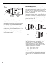
Setting Mic Levels
CAUTION! Adjust the Mic Level control
carefully
. Unlike the
Channel Selector switches, it will
not
rotate continuously!
The microphone input accommodates a wide range of mics
with typical sensitivity ratings of 1.5 mV (–56 dBV) to 15 mV
(–36 dBV) at 1 Pascal/94 dB SPL, while providing excellent
signal-to-noise ratios and maximum-acoustic-input levels.
1. Plug in the mic and power up the system.
2. Set the Mic Level control to the full clockwise (Hi) position.
Speak/sing into the microphone at typically-loud levels
while watching the Peak indicator on the receiver. If the
Peak indicator lights, turn the Mic Level control down
(counter-clockwise) only to the point where the indicator
light no longer illuminates. (When the AF Peak indicator
lights, the transmitter audio level is driving the receiver
into distortion. For best audio, the Mic Level should be
set as high as possible, but not so high as to light the
Peak indicator.)
3. Now, while speaking/singing into the microphone at
typically-loud levels, adjust the output level of the receiver
so the highest sound pressure level going into the
microphone causes no input overload in the camera/mixer,
and yet permits the camera/mixer level controls to operate
in their “normal” range (not set too high or too low). This
provides the optimum signal-to-noise for the entire system.
Setting Line Level – ATW-T101(x)
When using a Hi-Z line-level source with the ATW-T101(x)
transmitter, set the input level using the same method given
above. The Mic Level (MIC LVL) control adjusts audio gain for
both mic and line inputs.
RF Interference
Please note that wireless frequencies are shared with other
radio services. According to Federal Communications
Commission regulations, “Wireless microphone operations
are unprotected from interference from other licensed
operations in the band. If any interference is received by any
Government or non-Government operation, the wireless
microphone must cease operation . . .”
If you need assistance with operation or frequency selection,
please contact your dealer or the Audio-Technica professional
division.
Extensive wireless information also is available on the
Audio-Technica Web site at www.audio-technica.com.
7