11
Calibration Procedure for the BBE 362XL (REV/S/ON 1.1)
NOTE: THIS UNIT WAS TESTED AND CALIBRATED AT THE FACTORY.
THIS PROCEDURE IS FOR QUALIFIED PERSONNEL ONLY.
INITIAL SETTINGS:
1. BBE Process control VR2 and Lo Contour control VR1, threshold control VR3, and release control VR4 to minimum
(fully C.C.W.).
2. Power switch on and BBE function switch in, (BBE on position). Note: Since both channels are identical in calibration, only
channel A will be outlined. Channel B will be in brackets [ ]. The signal will be input into the corresponding channel
connector marked as 1 /4” phone jack TRS. The output will be monitored at the corresponding channel marked as 1/4”
phone jack TRS.
POWER SUPPLY TEST:
1. With your DVM set to D.C. volts, measure the positive end of C35. You should read less than +26vdc
2. With your DVM set to D.C. volts, measure the negative end of C39. You should read less than -26vdc.
3. Measure the D.C. voltage on Jmp27. Reading should be +12vdc, (+/- 0.8vdc).
4. Measure the D.C. voltage on Jmp22. Reading should be -12vdc, (+/- 0.8vdc).
BBE PROCESS TEST:
1. Input a 5khz signal ~ -lOdBu into channel A [B] input.
2. Measure the channel A [B] output with a DVM set to A.C. volts.
3 With the Process control at minimum, (fully C.C.W.), DVM should read -10.5dBu, (+/- 0.5dBu).
4. With the Process control at maximum, (fully C.W.), DVM should read -1.5dBu, (+/- 0.5dBu).
LO CONTOUR TEST:
1. Input a 50hz signal ~ -l0dBu into channel A [B] input.
2. Measure the channel A [B] output with a DVM set to A.C. volts.
3. With the Lo Contour control at minimum, (fully C.C.W.), DVM should read -9.5dBu, (+/- 0.5dBu).
4. With the Lo Contour control at maximum, (fully C.W.), DVM should read -1.5dBu, (+/- 0.5dBu).
BYPASS TEST: (NOTE: Lo Contour and Process controls at maximum)
1. Input a 500hz signal ~ -l0dBu into channel A [B] input.
2. Measure the channel A [B] output with a DVM set to A.C. volts.
3. With the Process in, the DVM should read -12dBu (+/- 0.5dBu) and the process LED should illuminate green
4. With the Process out, the DVM should read -10.5dBu (+/- 0.5dBu) and the process LED should illuminate red.
CLIP INDICATOR TEST:
1. Input a 500hz signal ~ +19dBu into the channel A [B] input.
2. Verify that the clip LED is on.
3. Change signal level to +16dBu and verify that the clip LED turns off.
Note: When both channels are driven, the clip indicator will turn on at +15dBu.
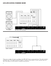
XLR BALANCED TEST:
Note: Remove all 1/4” phone plugs from output jacks.
2. Input a 500hz signal ~ -l0dBu into the channel A [B] input. Using your DVM, measure the A.C. voltage of channel A [B]
output across pin 2 and pin 3 of the channel XLR jack. ( Note: connect the Black lead of the DVM to pin 3 and the Red lead
of the DVM to pin 2).
3. Your DVM should read 4.0dBu (+/- 0.5dBu).
END OF TEST
5381 Production Drive
Huntington Beach, CA 92649
(714) 897-6766


