


6
XENYX 1622FX/1832FX/2222FX/2442FX
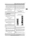
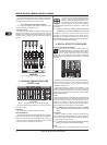
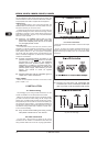
the MID control to set the amount of boost or cut, and the FREQ
control to determine the central frequency.
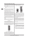
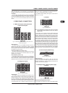
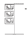
2.1.3 Monitor and effects busses (Aux sends)
Fig. 2.3: Aux Send control MON and FX in the channel strips
Monitor and effects busses (AUX sends) source their signals
via a control from one or more channels and sum these signals
to a so-called bus. This bus signal is sent to an aux send
connector (for monitoring applications: MON OUT) and then
routed, for example, to an active monitor speaker or external
effects device. In the latter case, the effects return can then be
brought back into the console via the aux return connectors.
All monitor and effects busses are mono, are tapped into post
EQ and offer amplification of up to +15 dB.
Pre-fader/post-fader
When using effects on a channel signal, it is usual to have the
aux send post fader so that the balance between effect and dry
signal stays constant even when the channel fader is altered. If
this were not the case, the effects signal of the channel would
remain audible even when the channel fader is turned all the way
down. For monitoring, the aux sends are generally pre-fader, i.e.
they operate independently of the position of the channel fader.
PRE
When the PRE switch is pressed down, the associated aux
send is taken pre-fader.
FX
The aux send marked FX offers a direct route to the built-in
effects processor and is therefore post-fader and post-mute.
Please refer to chapter 4 DIGITAL EFFECTS PROCESSOR for
detailed information.
+ If you are using the built-in effects processor, make
sure that STEREO AUX RETURN 3 has nothing plugged
into it (2442FX and 2222FX), otherwise the internal
effects return will be muted. This is not relevant if
you use the FX OUT jack to drive an external effects
device.
+ 1622FX and 1832FX: On these consoles, the above
note refers to the STEREO AUX RETURN 2 jacks as
these models do not have a dedicated effect output.
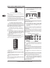
INSERT
Insert points enable the processing of a signal with dynamic
processors or equalizers. They are sourced pre-fader, pre-EQ
and pre-aux send. Detailed information on using insert points
can be found in chapter 5.3.
+ Unlike the 2442FX, the 1622FX, 1832FX and 2222FX
have their insert points located on the rear of the
console.
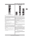
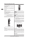
TRIM
Use the TRIM control to adjust the input gain. This control
should always be turned fully counter-clockwise whenever you
connect or disconnect a signal source to one of the inputs.
The scale has 2 different value ranges: the first value range
(+10 to +60 dB) refers to the MIC input and shows the
amplification for the signals fed in there.
The second value range (+10 to -40 dB) refers to the line input
and shows its sensitivity. The settings for equipment with st
andard line-level signals (-10 dBV or +4 dBu) look like this: While
the TRIM control is turned all the way down, connect your
equipment. Set the TRIM control to the external devices standard
output level. If that unit has an output signal level display, it should
show 0 dB during signal peaks. For +4dBu, turn up TRIM slightly,
for -10 dBV a bit more. Fine-tuning of a signal being fed in is done
using the level meter. To route the channel signal to the level
meter, you have to press the SOLO switch and set the MODE
switch in the main section to PFL (LEVEL SET).
Using the TRIM control, drive the signal to the 0-dB mark. This
way you have a vast amount of drive headroom for use with
very dynamic signals. The CLIP display should light up only rarely,
preferably never. While fine-tuning, the equalizer should be set
to neutral.
LOW CUT
Additionally, the mono channels of the mixing consoles have a
high-slope LOW CUT filter for eliminating unwanted, low-
frequency signal components (75 Hz, 18 dB/octave).
2.1.2 Equalizer
All mono input channels have a 3-band equalizer with semi-
parametric mid bands. All bands provide boost or cut of up to
15 dB. In the central position, the equalizer is off (flat).
The circuitry of the British EQs is based on the technology
used in the best-known top-of-the-line consoles and providing a
warm sound without any unwanted side effects. The result are
extremely musical equalizers which, unlike simple equalizers,
cause no side effects such as phase shifting or bandwidth
limitation, even with extreme gain settings of ±15 dB.
Fig. 2.2: Equalizer of the input channels
The upper (HIGH) and the lower (LOW) bands are shelving
filters that increase or decrease all frequencies above or below
their cut-off frequency. The cut-off frequencies of the upper
and lower bands are 12 kHz and 80Hz respectively. For the mid
range, the console features a semi-parametric equalizer with a
filter quality (Q) of 1 octave, tunable from 100 Hz to 8 kHz. Use
2. CONTROL ELEMENTS AND CONNECTORS