


7
XENYX 1622FX/1832FX/2222FX/2442FX
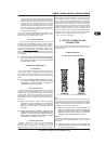
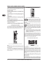
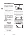
2.1.4 Routing switch, PAN, SOLO and channel fader
Fig. 2.4: The panorama and routing controls
and the channel fader
PA N
The PAN control determines the position of the channel signal
within the stereo image. When working with subgroups, you
can use the PAN control to assign the signal to just one output,
which gives you additional flexibility in recording situations. For
example, when routing to subgroups 3 and 4, panning hard left
will route the signal to group output 3 only, and panning hard
right will route to group output 4 only.
MUTE
The MUTE switch breaks the signal path pre-channel fader,
hence muting that channel in the main mix. The aux sends which
are set to post-fader are likewise muted for that channel, while
the pre-fader monitor paths remain active irrespective of whether
the channel is muted or not.
MUTE LED
The MUTE LED indicates a muted channel.
CLIP-LED
The CLIP-LED lights up when the input signal is driven too
high. If this happens, back off the TRIM control and, if necessary,
check the setting of the channel EQ.
SOLO
The SOLO switch is used to route the channel signal to the
solo bus (Solo In Place) or to the PFL bus (Pre Fader Listen). This
enables you to listen to a channel signal without affecting the
main output signal. The signal you hear is taken either before the
pan control (PFL, mono) or after the pan and channel fader
(Solo, stereo) (cf. chap. 2.3.10 Level meters and monitoring).
SUB (1-2 and 3-4)
The SUB switch routes the signal to the corresponding
subgroups. The 2442FX has 4 subgroups (1-2 and 3-4).
MAIN
The MAIN switch routes the signal to the main mix bus.
The channel fader determines the channels volume in the
main mix (or submix).
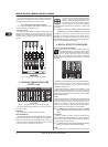
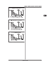
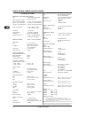
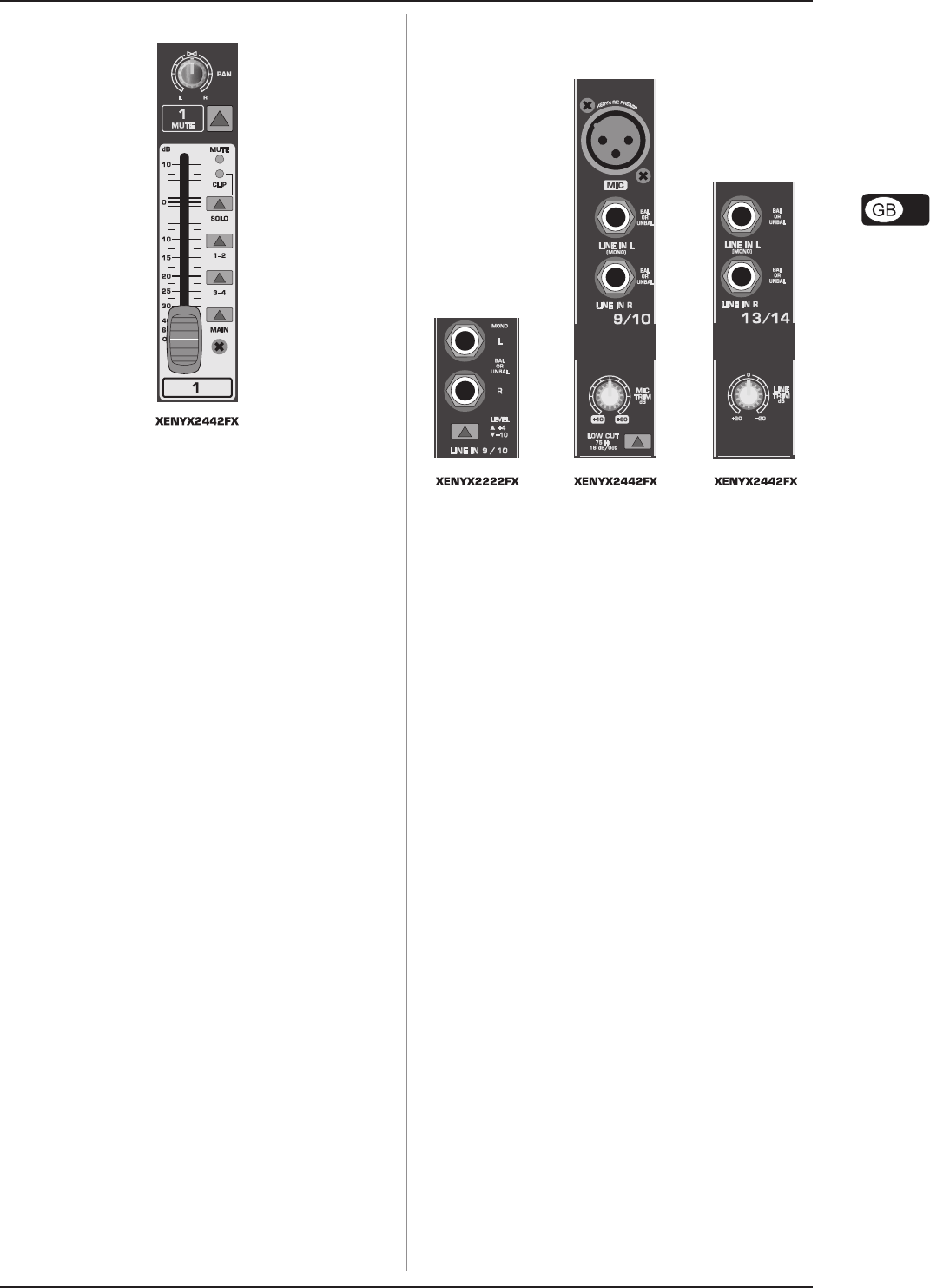
2.2 Stereo channels
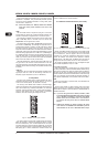
2.2.1 Channel inputs
Fig. 2.5: The various stereo channel inputs
Each stereo channel has two balanced line level inputs on
jacks for left and right channels. Channels 9/10 and 11/12 on the
2442FX feature an additional XLR microphone jack with phantom
power. If only the left jack (marked L) is used, the channel
operates in mono. The stereo channels are designed to handle
typical line level signals, and, depending on model, have a level
switch (+4 dBu or -10 dBV) and/or a line TRIM control. Both jack
inputs will also accept unbalanced connectors.
LOW CUT and MIC TRIM
These two control elements operate on the XLR connectors of
the 2442FX, and are used to filter out frequencies below
75 Hz (LOW CUT) and to adjust microphone levels (MIC TRIM).
LINE TRIM
Use this control to adjust the line signal levels on channels
13-16 (2442FX only).
LEVEL
For level matching, the stereo inputs on the 1622FX, 1832FX
and 2222FX have a LEVEL switch to select between +4dBu
and -10dBV. At -10dBV (homerecording level), the input is
more sensitive than at +4dBu (studio level).
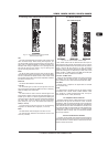
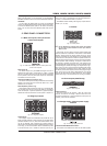
2.2.2 Equalizer stereo channels
The stereo channels contain a stereo EQ section. The cut-off
frequencies of the high and low bands are 12 kHz and 80 Hz
respectively, while the center frequencies of the high-mid and
low-mid bands are 3 kHz and 500 Hz respectively. The HIGH and
LOW controls have the same characteristics as the EQ in the
mono channels. Both mid range bands are of the peak filter type.
A stereo EQ is superior to two mono EQs on a stereo signal as
two separate EQs will usually result in a discrepancy between
left and right channels.
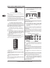
2.2.3 Aux sends stereo channels
In principle, the aux sends of the stereo channels function the
same way as those of the mono channels. As the aux sends are
mono, the send from a stereo channel is first summed to mono
before it reaches the aux bus.
2. CONTROL ELEMENTS AND CONNECTORS