


ENGLISH
PRO MIXER DJX700 User Manual
4
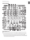
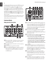
The TRIM control in the CHANNEL section is used to
{3}
adjust the level of the input signal. The level meter
{5}
reads the input level.
Each of the input channels features a 3-band equalizer
{4}
(HI, MID and LOW) with kill characteristic. Thus, the
signal can be attenuated to a much greater extent (-32 dB)
than it can be raised (+12 dB). This function can be very
useful when, for example, fading a frequency range out of a
music track.
The overall level also depends on the EQ setting. Thus,
◊
you should adjust the equalizer before setting the
input gain with the TRIM control.
The 10-digit LED chains display the signal level of the
{5}
input signals.
Adjust the channel volume using the CHANNEL fader.
{6}
Microphone channel
The MIC IN connector is the balanced XLR input for your
{7}
dynamic microphone.
Set the volume of the microphone signal with the TRIM
{8}
control in the MIC section.
There is a 3-band equalizer (HI, MID and LOW, no kill
{9}
characteristic) in the microphone section. This allows you
to ne-tune your voice to adapt perfectly to your sound.
Activate the microphone channel using the MIC ON
[10]
switch. The channel is active when the corresponding LED
is lit.
The PRO MIXER is equipped with a talkover function,
[11]
which works very simply: if you speak into the microphone
while a track is running, the volume of the music is auto-
matically reduced, so that your voice is always “in front”.
The TALK control allows you to determine how much the
music volume is lowered (max. -24 dB). This function can
come in handy when your own voice needs to be prominent-
ly heard, as in when making an announcement etc.
MONITOR section
The MONITOR signal is your headphones signal, allowing you
to listen to music without affecting the MASTER output signal.
When the MODE switch is in the “Split” position, channel
[12]
PFL is located on the left side of the stereo image, while
the MASTER signal is on the right. In this case, the MIX
control (see below) serves no function. While in “Stereo”
mode, you can use the MIX control to alternate between
MASTER signal and PFL.
When in “Stereo” mode, the MIX control lets you determine
[13]
which signal can be heard via the headphones. When the
control is turned to its left-most position (CUE), you hear
the headphone signal only; when the control is turned to
its right-most position, you hear the MASTER signal only.
Alternating the MIX control between the two end positions
lets you dermine the relative ratio between the two signals
in your headphones.
The Level control determines the volume of the head-
[14]
phones signal.
Connect you headphones using the unbalanced PHONES
[15]
OUT connector. Your headphones should have a minimum
impedance of 32 Ohms.
To select the PFL signal for the headphones, use the MON-
[16]
ITOR CUE keys (CH-1 to CH-4, MASTER, EFFECTS). You
can also select multiple signal sources and listen to them
simultaneously. LEDs on corresponding keys are lit when a
channel is routed to the headphones.
MASTER section
The LEVEL METER displays the level of the MASTER
[17]
signal.
The MASTER fader allows you to adjust the output volume
[18]
at the MASTER output (see
[44]
).
The MASTER BALANCE control for the MASTER output
[19]
is for setting the stereo image.
The BOOTH LEVEL control adjusts the output level of the
[20]
BOOTH output (see
[45]
).
Crossfader section
ASSIGN A and ASSIGN B selectors let you determine
[21]
which input signals are routed to CROSSFADER sides A
and B. You can also alternate between these two signals by
using the CROSSFADER (see below).
The VCA controlled CROSSFADER is used to fade between
[22]
the channels you have selected (see
[21]
). Like the channel
faders, the crossfader section is equipped with a profes-
sional 45-mm fader.
The TIME OFFSET LED indicates the synchronisation of
[23]
tracks (see chapter 2.7).
The TEMPO DIFFERENCE LED displays tempo differ-
[24]
ences between the tracks (see chapter 2.7).
A 3-band kill switch is available for use with both the left
[25]
and the right side of the crossfader (KILL A and KILL B
respectively). Kill switches are used to lower three separate
frequency ranges (LOW, MID and HIGH) up to -32 dB.
When using the kill switch, the equalizer of ordinary DJ
mixers usually loses its functionality. Not the case with
the DJX700: the EQs can be used to achieve an even more
pronounced lowering of a particular frequency range.
The CF CURVE control lets you alter the control character-
[26]
istic of the crossfader between linear and logarithmic in an
inte number of steps. When set to linear, the crossfader