


7 PRO MIXER DJX900USB User Manual
When you have limited the tempo of the tracks on both channels with the
SYNCLOCK or BEAT ASSIST buttons, the dierence in tempo from both channels
is illustrated in the form of a nine-character message on the TEMPO DIFFERENCE-
LED (24). The extent of the dierence in tempo is indicated by a corresponding
swing to the right (signal A is slower) or to the left (signal B is slower). When the
middle LED lights up, the tempi are the same. The TIME OFFSET LED (23) below
that displays the signal A and B synchronisation. Should the middle LED light
up, the tracks are synchronised. Should the display move to the left or right,
thechannels are not synchronised. TheTEMPO DIFFERENCE and TIME OFFSET
displays are only active if the tempi of both channels have been xed in one of
the waysdescribed.
◊ When no signal is present (or when the signal level is too low), the BPM
display shows only dashes. When the signal is present but can not
be identified, the display shows 160 BPM and then shows the said
dashes. The beat counter then attempts to get another readout.
Therefore, “160” BPM is no usable value; rather, it is simply an error
message when the signal can not be analyzed.
To exit the SYNC LOCK or BEAT ASSIST modes, simply push the SYNC LOCK button
once more on both channels.
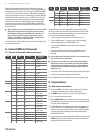
8. Internal Eects Processor
8.1 Presets of the multi-eects processor
Grp No. Eect Type
Adjustable
Parameter
1
0 Filter Sweep LP Frequency
1 Filter Sweep BP Frequency
2 Filter Sweep HP Frequency
3
Auto Filter
(Envelope)
LP Sensitivity
4
Auto Filter
(Envelope)
BP Sensitivity
5
Auto Filter
(Envelope)
HP Sensitivity
6 LFO Filter LP LFO Rate
7 LFO Filter BP LFO Rate
8 LFO Filter HP LFO Rate
2 0 Bitcrusher — Depth
3
0 Flanger Gate/Pan LFO Rate
1 Flanger Standard (Full Res) LFO Rate
2 Flanger Standard (Half Res) LFO Rate
3 Flanger Ultra LFO Rate
4
0 Delay 1/1
Delay Time
(related to BPM)
1 Delay 3/4
Delay Time
(related to BPM)
2 Delay 1/2
Delay Time
(related to BPM)
5
0 Echo 1/1
Delay Time
(related to BPM)
1 Echo 3/4
Delay Time
(related to BPM)
2 Echo 1/2
Delay Time
(related to BPM)
6
0 Reverb Big Plate Reverb Time (Decay)
1 Reverb Small Chamber Reverb Time (Decay)
2 Reverb Bright Room Reverb Time (Decay)
3 Reverb Voice Widener Tone
4 Reverb/Delay Big Plate + Delay
Delay Time
(related to BPM)
Grp No. Eect Type
Adjustable
Parameter
7
0 Phase Shifter 4 LFO Rate
1 Phase Shifter Fall LFO Rate
2 Phase Shifter Rise LFO Rate
8
0 Panning Panning LFO Rate
1 Panning Tremolo LFO Rate
9
0 Sim/Dyn Ultrabass Frequency
1 Sim/Dyn Ultrafex Frequency
2 Sim/Dyn Voice Changer Distortion
The DJX900USB features an internal digital eects processor into which you
can feed your master signal, the signals of the input channels or the mic signal.
Themodule provides a number of standard eects, such as reverb, delay and
echo, as well as various lter and modulation eects.
• To select the signal to be processed, use the SOURCE selector (33).
• Turn the PROGRAM control (35) to select an eect. The corresponding
program number appears on the PROGRAM display (34).
• Press and hold the PROGRAM control for about 2 seconds to load the
selectedpreset.
• When the new eect has been loaded, turn the PROGRAM control (35)
to change the eect’s parameters. The parameter value is shown on
thedisplay.
◊ View the table (column “Ajustable Parameter”) to see which parameter
of the selected effect can be modified.
◊ The parameter values of the delay and echo effects are displayed in
BPM (beats per minute). The selectable range is from 80 to 160 BPM.
The display only shows two digits and so values of 100 and above are
represented with a dot behind the number (for example, 120 BPM is
displayed as “20.”).
• Use the LEVEL control (36) to determine the volume level of the eect signal.
• Activate the eect signal by pressing the FX ON switch (37).
Press the PROGRAM control one more time to use it for selecting eects again.
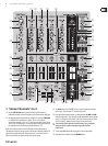
9. Connections
9.1 Rear panel connectors
(38) These are the LINE i. e. CD inputs to connect a tape deck, CD or MD player
etc. Unlike other channels, channel 1 features two line inputs.
(39) The PHONO inputs for channels 2 to 4 are for connecting a turntable.
(40) The � connectors ground the turntables.
(41) With the PHONO/LINE switch it is possible to switch the input sensitivity of
the PHONO inputs 2 to 4 to line level. This allows you to connect a tape deck
or a CD player to the PHONO inputs.
(42) The DJX900USB features an integrated eects loop for the connection of an
external eects device. The MONITOR signal is taken at the SEND output
and routed, for example, to a reverb processor. Thus, the signal at the SEND
connector is identical to the headphones signal and is selected with the
MONITOR CUE buttons (16).
(43) The externally processed signal is added to the MASTER output signal via the
RETURN connectors. The eect signal volume may only be adjusted at the
output control of the eects device itself.