


11
FEEDBACK DESTROYER PRO FBQ2496
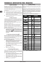
9. SPECIFICATIONS
Audio inputs
Connections XLR and 1/4" TRS stereo connector
Type electronically balanced input
Input impedance approx. 20 kΩ balanced
Nominal input level -10 dBV / +4 dBu (adjustable)
Max. input signal level +20 dBu at +4 dBu nominal level,
+6 dBV at -10 dBV nominal level
typically -40 dB
Audio outputs
Connections XLR and 1/4" TRS stereo connector
Type balanced
Output impedance approx. 200 Ω balanced
Max. output level +20 dBu at +4 dBu nominal level,
+6 dBV at -10 dBV nominal level
Bypass
Type Relay, hard bypass in case of
power outage
System information
Frequency response <10 Hz to 44 kHz
Dynamic range 107 dB
THD 0.007 % typically @ +4 dBu, 1 kHz,
amplification 1
Crosstalk < -100 dB @ 1 kHz
MIDI interface
Type 5-pole DIN connectors IN/OUT/THRU
Digital processing
Converter 24 Bit / 96 kHz
Sample rate 96 kHz
Parametric equalizer (PEQ)
Type max. 20 independent, fully
parametric filters per channel
Frequency range 20 Hz to 20 kHz
Bandwidth 1/60th to 10 octaves
Possible value range +15 to -36 dB
Feedback Destroyer (FBQ)
Type digital signal analysis for feedback
recognition purposes
Filter max. 20 digital notch filters per channel
Frequency range 20 Hz to 20 kHz
Bandwidth 1/60th octave
Possible value range 0 to -36 dB
Display
Type 3-digit numeric LED display
POWER SUPPLY
Mains voltage 100 - 240 V~, 50 - 60 Hz
Power consumption approx. 10 W
Fuse T 1 A H 250 V
Mains connector Standard receptacle
DIMENSIONS/WEIGHT
Dimensions (H x W x D) approx. 44.5 mm x 482.6 mm x 190.5 mm
(approx. 1 ¾" x 19" x 7 ½")
Weight approx. 1.9 kg (4.2 lbs)
BEHRINGER is constantly striving to maintain the highest professional standards. As a result
of these efforts, modifications may be made from time to time to existing products without prior
notice. Specifications and appearance may differ from those listed or illustrated.
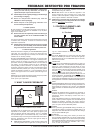
8. INSTALLATION
8.1 Installation in a rack
The FBQ2496 requires one height unit (1 HE) for mounting in a
19" rack. Please keep in mind that an additional 10cm (4") of
depth in the back are required to enable trouble-free access to the
connectors on the rear panel.
For rack installation, please use M6 machine screws and nuts.
Please make sure that your FBQ2496 has enough cooling air, and
never put it on an amp or other heat-emitting equipment to avoid
overheating.
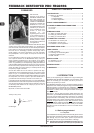
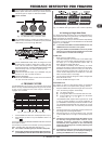
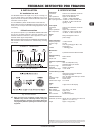
8.2 Audio connections
The inputs and outputs on your FEEDBACK DESTROYER PRO
are laid out completely balanced. Whenever possible, try to
establish balanced connections to other equipment in order to
maximize disturb signal compensation.
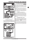
MIDI connections (IN/OUT/THRU) are established using the standard
DIN connectors. Data transmission is achieved using a floating
opto-coupler.
Fig. 8.1: 1/4" TRS connector
Fig. 8.2: XLR connector
+ Make sure that only competent people install your
FBQ2496. They must be sufficiently earthed during and
after the installation; otherwise, electrostatic discharges
may negatively affect the operating characteristics of your
equipment.
9. SPECIFICATIONS