


8
FEEDBACK DESTROYER PRO FBQ2496
4.2 Setting up parametric filters
Some or even all 40 filters on your FBQ2496 can be deployed as
parametric filters. They have to be set up in a targeted fashion,
with great precision. The frequency, bandwidth and gain parameters
are available.
Selecting the number of parametric filters
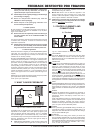
1. Keep the PEQ button pressed
for a few moments. The LED
on the PEQ button blinks, and the display shows the current
number of parametric filters (p 0 = no parametric filters
deployed, P20 = all filters are parametric). Additionally, the
LEDs on the deployed Single-Shot filters are lit.
2. You can use the wheel to change the number of parametric
filters.
The display shows the number of deployed parametric filters,
and the corresponding LEDs in the status display (
) are
lit.
3. Pressing the PEQ button again briefly completes the
procedure.
+ Now, the only parametric filters whose LEDs are still lit
are those whose gain (either positive or negative) does
not equal zero.
Setting up frequency, bandwidth, gain
You should implement the following procedure with each individual
parametric filter:
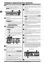
1. Briefly press the PEQ button.
The LED on the PEQ button is lit. The display indicates the
number of the selected filter (e.g. 19).
2. Use the wheel to select the parametric filter whose values
you wish to modify.
+ Any filter may be selected using the wheel! However, the
parameters of the Single-Shot and automatic filters can
only be displays and can not be modified!
3. After you press the FREQUENCY button, use the wheel to set the
filter mid frequency (the LED on the button blinks).
You can get a precise readout of the set mid frequency by
observing the display and the status of the Hz/kHz LED next to it.
To modify exactly the frequency band you have in mind, you can
shift the filters bandwidth.
4. Briefly press the BANDWIDTH button.
5. Turning the wheel changes the filter
s bandwidth. The 1/60
LED lights up if a value lower than 0.1 is set (1 x 1/60,
2 x 1/60 ... 5 x 1/60). In case of larger bandwidths, the value
is shown directly in the display (0.1, 0.2 ... 1.0, 1.1 ... 10.0).
A parametric filter becomes engaged only after an increase/
decrease of the set frequency is entered:
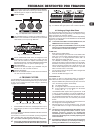
6. Briefly press the GAIN button. The LED on the button is lit. At
the same time, the dB LED under the 3-digit display is also
lit.
7. The gain can be adjusted using the wheel. The available
values range from 15 dB to - 36 dB (can be changed in
0.5-dB increments in the +15 dB to -15dB range; in 1-dB
increments in the -16 to -36 dB range). The value is shown in
the display.
+ The FBQ2496 has a 3-digit display. Positive values are
easily represented (14, 14.5, 15). For negative values,
complete representation would require 4 digits. However,
because the display only shows 3 digits, the position after
the decimal point is omitted and replaced by a dot to the
right of the first two digits (-15, -14.(5), -14, -13.(5)),
which stands for the missing decimal value.
8. Press the PEQ button briefly again to complete the procedure.
+ The status display only shows the filters whose gain does
not equal to zero (either positive or negative).
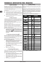
4.3 Setting up automatic filters
The number of automatic filters can not be separately set. It results
from the number of fixed and parametric filters (fig. 4.2).
+ To lower the number of automatic filters, increase the
number of Single-Shot and/or parametric filters.
The automatic filters automatically spring into action on a per-
need basis during a performance or a recording session. Of course,
having the FBQ2496 react to changing situations would be
desirable. To allow for this, you need to establish a setup in which
the automatic filters are only periodically active, setting themselves
back to zero afterwards in order to be ready for the next instance in
which feedback is occurring.
The so-called Filter Lifting Time informs you about how long a
filter set to automatic may remain active before its values are reset
back to zero. This Filter Lifting Time can be set on the FBQ2496.
1. Press the FILTER LIFT button. The LED on the button starts to
blink.
2. Using the wheel, Filter Lifting Time can either be turned off
(off) or can be set to 1 min, 5 min, 10 min, 30 min or 60 min.
3. To exit this menu, press the FILTER LIFT button again. The
LED no longer blinks.
4. If a Filter Lifting Time value has been set (i.e. any value
other than off!), the button LED is lit.
+ If a satisfactory setting for the Single-Shot and automatic
filters has been achieved, you can keep this setting by
pressing the FREEZE button. The display shows: -.
5. CONNECTIVITY OPTIONS
+ The FEEDBACK DESTROYER PRO is not intended to be
connected directly to the microphones! If this is
unavoidable, then we recommend our proven
BEHRINGER SHARK DSP110 instead, which is equipped
with a dedicated microphone preamplifier.
+ No amount of fancy gear can undo the mistakes committed
when selecting the locations for microphones! Therefore,
when you set up your mics, use them according to their
directivity and feedback susceptibility.
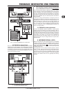
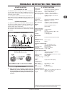
5.1 FBQ2496 in the monitor path
Due to its 2-channel architecture, the FBQ2496 is ideal for use
with two monitor paths. Connect your mixing console
s pre-fader
aux outputs to the FBQ2496 inputs, as shown in fig. 5.1. The
monitor power amp inputs are then connected to the FBQ2496
outputs.
Using the FBQ2496 in the monitor path can considerably augment
the volume level.
5. CONNECTIVITY OPTIONS